Applicable to OS V1.7
The LightOnOffDimming1Switch component allows for a light control with a dimming function. The component is designed for a single switch (one button connected to the digital input), which can work in two modes, short and long press:
-
the short press (if the Switch slot is set to true for the time shorter than defined in the Long Press Time slot) triggers a toggle function - each short press sets the 0 or the Maximum Light Level value on the output slot,
-
the long press increases or decreases the lighting level; each long press toggles between increasing and decreasing the lighting level.
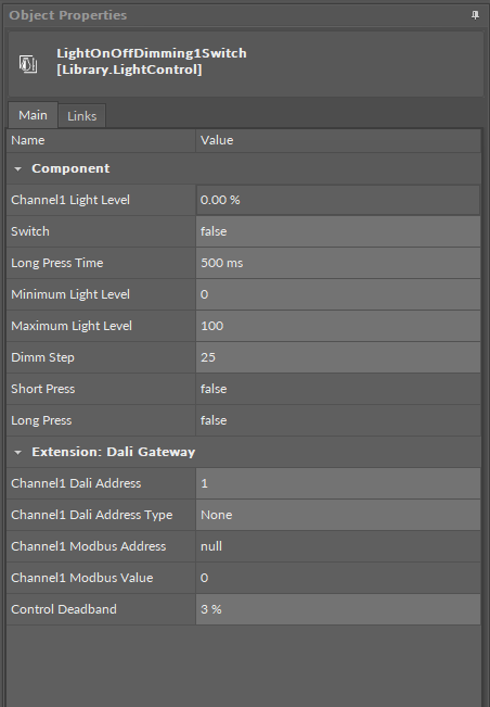
The LightOnOffDimming1Switch component has the following slots:
-
Channel1 Light Level: shows the output light brightness level;
-
Switch: receives a signal from a connected monostable switch; on a rising edge switches on/off or increases/decreases the intensity of the light;
-
Long Press Time: defines the time for the long press function, by default, 500 ms;
-
Minimum Light Level: allows to set the minimum value of channel 1 light level;
-
Maximum Light Level: allows to set the maximum value of channel 1 light level;
-
Dimm Step: defines the number of steps between the minimum and maximum light levels for which the light can be dimmed;
-
Short Press: indicates if the switch has been pressed for a time shorter than the Long Press Time;
-
Long Press: indicates if the switch has been pressed for a time longer than the Long Press Time.
DALI Extension
The DALI extension enhances the component’s functionality by providing a possibility to work through the DALI protocol. The extension allows to determine the DALI device or group of DALI devices to control. With the use of the extension it is also possible to broadcast DALI commands to all connected devices.
The extension is added from the context menu of the component (Add Extension>DALI Gateway).
To process the light control, the LightOnOffDimming1Switch/LightOnOffDimming2Switch component has to be linked to the network point component:
-
the Channel1 Modbus Address slot should be linked to the Modbus network point’s Address slot,
-
the Channel1 Modbus Value slot should be linked through the Data Point to the Modbus network point.
The two above values determine the value to send and the address of the DALI device to send the command to.
-
Channel1 Dali Address: sets the short address of the DALI device or a group DALI devices to be controlled by the component,
-
Channel1 Dali Address Type: allows to set a proper Modbus address slot for a linked network point depending on a number of DALI devices to be controlled (single/group/all),
-
Available values:
-
None: Modbus address is null,
-
Single: Modbus address is 510,
-
Group: Modbus address is 520,
-
All: Modbus address is 530;
-
-
-
Channel1 Modbus Address: the output slot with the Modbus address indicating the destination DALI device to send the DALI command to;
-
Channel1 Modbus Value: the 16-bit output value comprised as follows:
-
upper 8 bits: 15-8:
-
short address of a single lamp 0-63 for lamp 1 to 64, or
-
short address of a group of lamps 0-15 for a lamp group 1 to 16;
-
-
lower 8 bits: light intensity 0-254.
-
The Channel1 Modbus Value value is set according to the formula:
Channel1 Modbus Value = (Channel1 Dali Address - 1) * 256 + Channel1 Light Level,
where:
Channel1 Dali Address = short DALI device address or DALI group address;
Channel1 Light Level = 0-254 value corresponding to the % out value of the Channel1 Light Level slot.
-
Control Deadband: allows to set a range of value (in %) which does not trigger any change of the Channel1 Modbus Value.
If the value of the Channel1 Light Level plus the Dimm Step values reach 0 or 254 (depending on the dimming direction, increase or decrease), the component sets the Channel1 Modbus Value to 0 or 254 in a lower byte (8 bits).