Applicable to OS V1.7
The LightControlWithCLC2Switch is an advanced component for controlling the light, either by constant light control or manual dimming. It supports two zones, a double switch, an occupancy sensor, and an occupancy runtime.
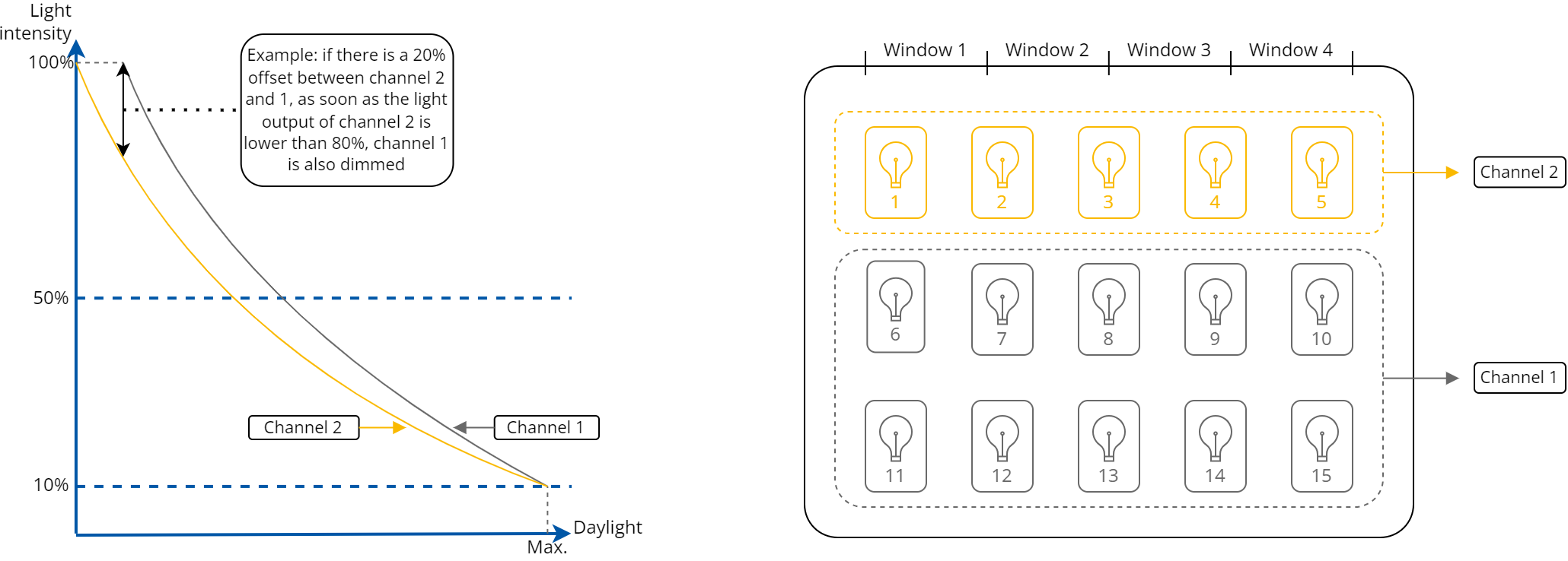
It can logically split the lamps into 2 groups (channels):
-
channel 1: located near the wall without the windows,
-
channel 2: located near the windows, which provide additional sunlight.
Because of an additional light source from windows, the lights in channel 2 can be controlled to be dimmer compared to the lights in channel 1.
Operating Modes
Under normal circumstances, the LightControlWithCLC2Switch component controls the light intensity based on the outcome of the Constant Light Control (CLC) PID control loop taking into account the occupancy factor. In certain cases, the CLC control loop can be overridden by using a manual dimming switch (dimming mode), direct command from the BMS (BMS mode), or an emergency mode.
CLC Mode
Occupancy Runtime
Occupancy runtime is a factor which impacts the functioning of the CLC control loop. While the occupancy sensor detects presence and during the time set in the Occupancy Runtime slot, the Light Enable and Channel1/Channel2 Light Level slots remain active. Occupancy runtime can be reset by pressing a button or by a signal from the occupancy sensor. The runtime timer starts counting down when the light is lit (either by a push button or an occupancy sensor).
The CLC mode operation is based on an integrated PID controller, which aims to achieve a set lux level by controlling the light levels of channel 1 and 2 as measured by a sensor connected to the Lux Sensor slot.
In the CLC mode, it is possible to set an offset between channels 1 and 2 to compensate for the additional light provided by windows. Example response from the PID controller in such a scenario can be seen in the figure below.
Time shift between channels
The important thing is that the controller needs to react fast for sudden light level drops (i.e., cloud obstructing the sun), but it should react more slowly in the opposite situation (sky clearing up). This is due to human perception of light and the fact that it is usually better perceived to have more light than not enough, while sudden changes in the light intensity are recognized as annoying.
This feature can be adjusted by the user by changing the Ramp Time slot value, which is the filtering time that slows down the control loop when the light should be dimmed down. By default, this value is set to 5 minutes.
CLC Control Cases
-
Light Enable: false, Occupancy Runtime: expired
-
light is switched off,
-
a short press of a switch (a rising edge on the Switch On slot) or a signal from an occupancy sensor results in turning on the light (the Light Enable slot set to true) and the light levels of channels 1 and 2 are controlled by the PID control loop according to the lux setpoint; occupancy runtime gets activated;
-
-
Light Enable: false, Occupancy Runtime: not expired
-
a signal from the occupancy sensor renew the runtime,
-
a short press on a switch (a rising edge on the Switch On slot) turns on the light and renews the runtime;
-
-
Light Enable: true, Occupancy Runtime: not expired
-
a signal from the occupancy sensor renew the runtime,
-
a short press on a switch (a rising edge on the Switch Off slot) turns off the light and renews the runtime;
-
-
Light Enable: true, Occupancy Runtime: expired
-
the light is turned off.
-
Dimming mode
The dimming mode overrides normal operation of the CLC control loop on a long press of the two-button switch. In this mode, light levels of channels 1 and 2 are controlled by the Switch On/Switch Off inputs (a long press performs dimming). Switch On is used to turn on the light (short press) or for dimming up (long press). Switch Off is used to turn off the light (short press) or for dimming down (long press).
Dimming Mode Control Cases
-
Light Enable: false
-
a long press of the switch results in turning on the light (the Light Enable slot set to true) and light levels of channels 1 and 2 dim up/down. If the switch is pressed is constantly (e.g., for 5 seconds), each time the long press time passes (by default, 500 ms), light levels of channels 1 and 2 will increase by the value of the Maximum Light Level divided by the Dimm Step (starting from the value in the Stored Reg Value slot);
-
if the light is turned on, each detected long press starts dimming the light levels of channels 1 and 2 by a step and interval defined in the Dimm Step and Long Press Time parameters, starting with dimming up/down depending on which switch is pressed;
-
each long press resets the occupancy runtime counter;
-
a signal from the occupancy sensor resets the runtime counter;
-
a short press resets the component to work in the CLC mode;
-
-
Light Enable: true, Control Mode: CLC
-
a long press of the switch, the dimming up/down starts from the current light level;
-
each long press starts dimming the light levels of channels 1 and 2 by a step and interval defined in the Dimm Step and Long Press Time parameters, starting with dimming up;
-
each long press resets the occupancy runtime counter;
-
a signal from the occupancy sensor resets the occupancy runtime counter;
-
a short press turns off the light and the light levels of channels 1 and 2 are set to 0, control mode is set to CLC.
-
BMS Mode
The BMS mode can be activated only when the light is turned off (the Light Enable slot is false). It is activated by providing a true value to the BMS Input. Once activated, light levels of channels 1 and 2 will be set to predefined values (separate for both channels, specified in the Channel1/Channel2 Bms Light Level parameters) and the Light Enable slot will be set to true. This mode is deactivated once the BMS Input is set to false or another mode is activated (either by a button or an occupancy sensor).
Emergency Mode
The emergency mode overrides all other modes as long as the Emergency Input stays true. If activated, the Light Enable is set to true and the light levels of channels 1 and 2 are set to a predefined common value (specified in the Emergency Light Level parameter). When going back to normal operation, both Light Enable and light levels of channels 1 and 2 are controlled by the last operation mode in use.
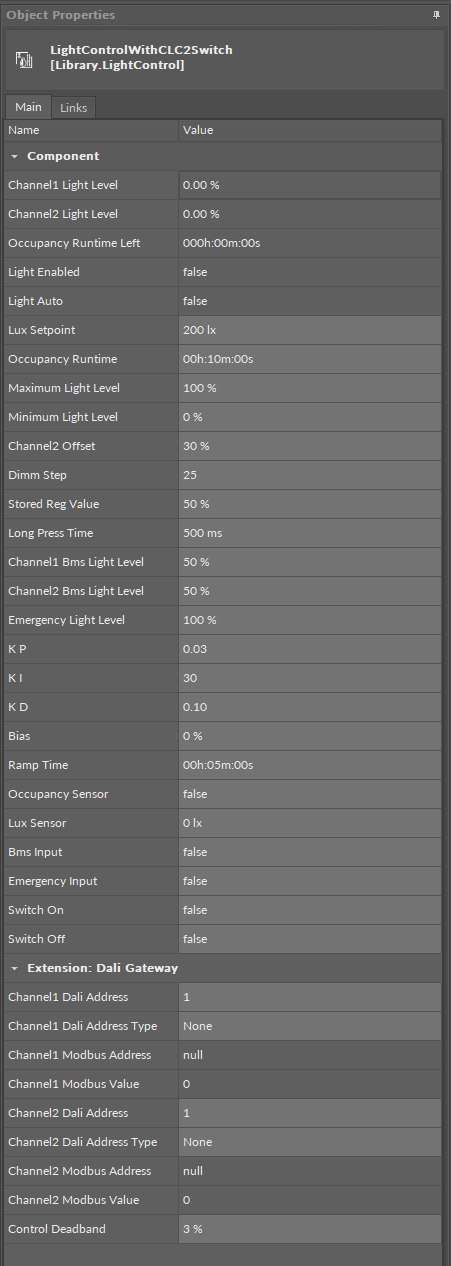
Slots
The LightControlWithCLC2Switch component has the following slots:
-
Channel1/Channel2 Light Level: shows the calculated channel 1 or 2 light intensity setpoint;
-
Occupancy Runtime Left: shows the time left until the occupancy runtime expires;
-
Light Enabled: shows that the light is turned on (true) or off (false) as a result of any of the operating modes: the CLC mode, dimming mode, BMS mode, or emergency mode;
-
Light Auto: shows that the light is turned on (true) or off (false) as a result of any of the CLC mode;
-
Lux Setpoint: allows to set the setpoint for the CLC control loop;
-
Occupancy Runtime: allows to set the time to uphold the occupancy when detected by the occupancy sensor and after the occupancy sensor no longer detects presence;
-
Maximum Light Level: allows to set the maximum value of channel 1 and 2 light level in the dimming and CLC modes;
-
Minimum Light Level: allows to set the minimum value of channel 1 and 2 light level in the dimming and CLC modes;
-
Channel2 Offset: allows to set the value for the light level offset between channel 1 and 2 (only in the CLC mode);
-
Dimm Step: defines the value of light intensity increase or decrease every long press;
-
Stored Reg Value: allows to set the value that would be stored after the dimming mode is turned off; next time a short press occurs, the lights are turned on with intensity defined in this slot; by default, this value is written from the Channel1/Channel2 Light Level slot taken right before the Occupancy Runtime changes to expired;
-
Long Press Time: defines the time for the long press function, by default, 500 ms;
-
Channel1/Channel2 Bms Light Level: allows to set the light levels of channel 1 or 2 when the operating mode gets overridden by BMS;
-
Emergency Light Level: allows to set the light levels of channel 1 and 2 when the operating mode gets overridden by emergency;
-
KP/KI/KD/Bias: allows to set the KP, KI, KD, bias parameters for the CLC control loop;
-
Ramp Time: defines the filtering time that slows down the control loop when light should be dimmed down;
-
Occupancy Sensor: receives the signal from the occupancy sensor (true: occupied, false: unoccupied);
-
Lux Sensor: receives the signal for the light level sensor;
-
Bms Input: receives the signal from the BMS and activates the BMS mode;
-
Emergency Input: receives the emergency signal and activates the emergency mode;
-
Switch On: receives a signal from a connected monostable switch; on a rising edge switches on or increases the intensity of the light;
-
Switch Off: receives a signal from a connected monostable switch; on a rising edge switches off or decreases the intensity of the light.
DALI Extension
The DALI extension enhances the component’s functionality by providing a possibility to work through the DALI protocol. The extension allows to determine the DALI device or group of DALI devices to control. With the use of the extension it is also possible to broadcast DALI commands to all connected devices.
The extension is added from the context menu of the component (Add Extension>DALI Gateway).
To process the light control, the LightControlWithCLC1Switch/LightControlWithCLC2Switch component has to be linked to the network point component:
-
the Channel1/Channel2 Modbus Address slots should be linked to the Modbus network point’s Address slot,
-
the Channel1/Channel2 Modbus Value slots should be linked through the Data Point to the Modbus network point.
The above values determine the value to send and the address of the DALI device to send the command to.
-
Channel1 Dali Address: sets the short address of the DALI device or a group DALI devices of channel 1 to be controlled by the component,
-
Channel1 Dali Address Type: allows to set a proper Modbus address slot for a linked network point depending on a number of DALI devices of channel 1 to be controlled (single/group/all),
-
Available values:
-
None: Modbus address is null,
-
Single: Modbus address is 510,
-
Group: Modbus address is 520,
-
All: Modbus address is 530;
-
-
-
Channel1 Modbus Address: the output slot with the Modbus address indicating the destination DALI network point of channel 1 to send the DALI command to;
-
Channel1 Modbus Value: the 16-bit output value comprised as follows:
-
upper 8 bits: 15-8:
-
short address of a single lamp 0-63 for lamp 1 to 64, or
-
short address of a group of lamps 0-15 for a lamp group 1 to 16;
-
-
lower 8 bits: light intensity 0-254.
-
To avoid sending to many requests by the DALI gateway, the Channel1/2 Modbus Vaule slot would be updated every time the light level is higher or lower by 3% than one previously set on the output. This value can be set in the Control Deadband slot.
-
Channel2 Dali Address: sets the short address of the DALI device or a group DALI devices of channel 2 to be controlled by the component,
-
Channel2 Dali Address Type: allows to set a proper Modbus address slot for a linked network point depending on a number of DALI devices of channel 2 to be controlled (single/group/all),
-
Available values:
-
None: Modbus address is null,
-
Single: Modbus address is 510,
-
Group: Modbus address is 520,
-
All: Modbus address is 530;
-
-
-
Channel2 Modbus Address: the output slot with the Modbus address indicating the destination DALI network point of channel 2 to send the DALI command to;
-
Channel2 Modbus Value: the 16-bit output value comprised as follows:
-
upper 8 bits: 15-8:
-
short address of a single lamp 0-63 for lamp 1 to 64, or
-
short address of a group of lamps 0-15 for a lamp group 1 to 16;
-
-
lower 8 bits: light intensity 0-254.
-
The Channel1/2 Modbus Value value is set according to the formula:
Channel1 Modbus Value = (Channel1/2 Dali Address - 1) * 256 + Channel1/2 Light Level,
where:
Channel1/2 Dali Address = short DALI device address or DALI group address;
Channel1/2 Light Level = 0-254 value corresponding to the % out value of the Channel1 Light Level slot.
-
Control Deadband: allows to set a range of value (in %) which does not trigger any change of the Channel1/2 Modbus Value.