Controller Overview
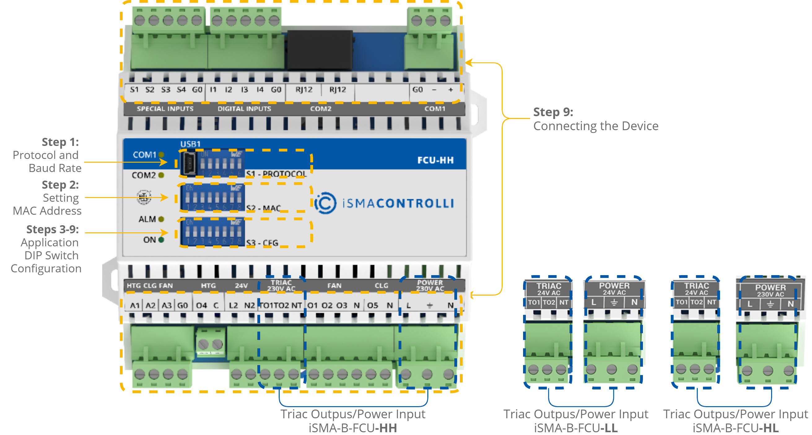
This section outlines the differences between the FCU hardware versions and describes steps required to properly configure the controller. For further information, please see the FCU Hardware manual.

The PROTOCOL DIP switch is responsible for configuring the communication protocol.
The MAC DIP switch is responsible for addressing the controller.
The CFG DIP switch is responsible for configuring the application.
Note: The detailed information about the DIP switches configuration is available in the FCU Hardware manual.
The iSMA-B-FCU controller configuration step by step is described in chapter 3 of this document and consists of steps:
-
Step 1: Selecting Protocol and Baud Rate; Restoring the Default Settings -
Step 2: Setting Controller Address -
Step 3: Choosing the FCU Pipe Type -
Step 4: Switching Between 1 Heating Stage and 2 Heating Stages Modes -
Step 5: Switching Between 1 Cooling Stage and 2 Cooling Stages Modes -
Step 6: Selecting Type of Control Required by the FCU Valves and Connection Details -
Step 7: Selecting the Temperature Control Value Source and its Connection Details -
Step 8: Selecting Type of Fan Used Within the Project and its Connection Details
Steps 3-8 describe configuration of the CFG DIP switch. Their overview with default positioning is presented in the table below.
|
No. |
Name |
On |
Off |
Default |
|
|---|---|---|---|---|---|
|
1 |
Pipe Mode |
2-pipe |
4-pipe |
4-pipe |
|
|
2 |
Heating 2nd Stage |
Enable |
Disable |
Disable |
|
|
3 |
Cooling 2nd Stage |
Enable |
Disable |
Disable |
|
|
4 |
Heating/cooling control mode |
Analog |
Digital |
Digital |
|
The CFG DIP switch configuration
WARNING!
Before attempting to configure the controller, make sure to have acquainted with all the required documentation, or have a good knowledge of the fan coil unit application–this will make configuration of the controller easy-going and trouble-free.
