4-Pipe System
In the 4-pipe system mode, the switch number 1 has to be set to the OFF position as shown in figure below. By default, this mode is ON.
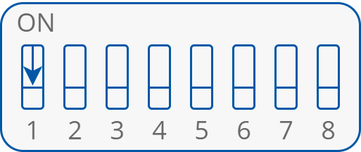
4-pipe system DIP switch configuration
In this configuration, the fan coil unit is equipped with two separate heating and cooling devices. The electric connection for the actuators of 24 V AC heating and cooling valves controlled by analog signal (0-10 V DC) is presented in the figure below.
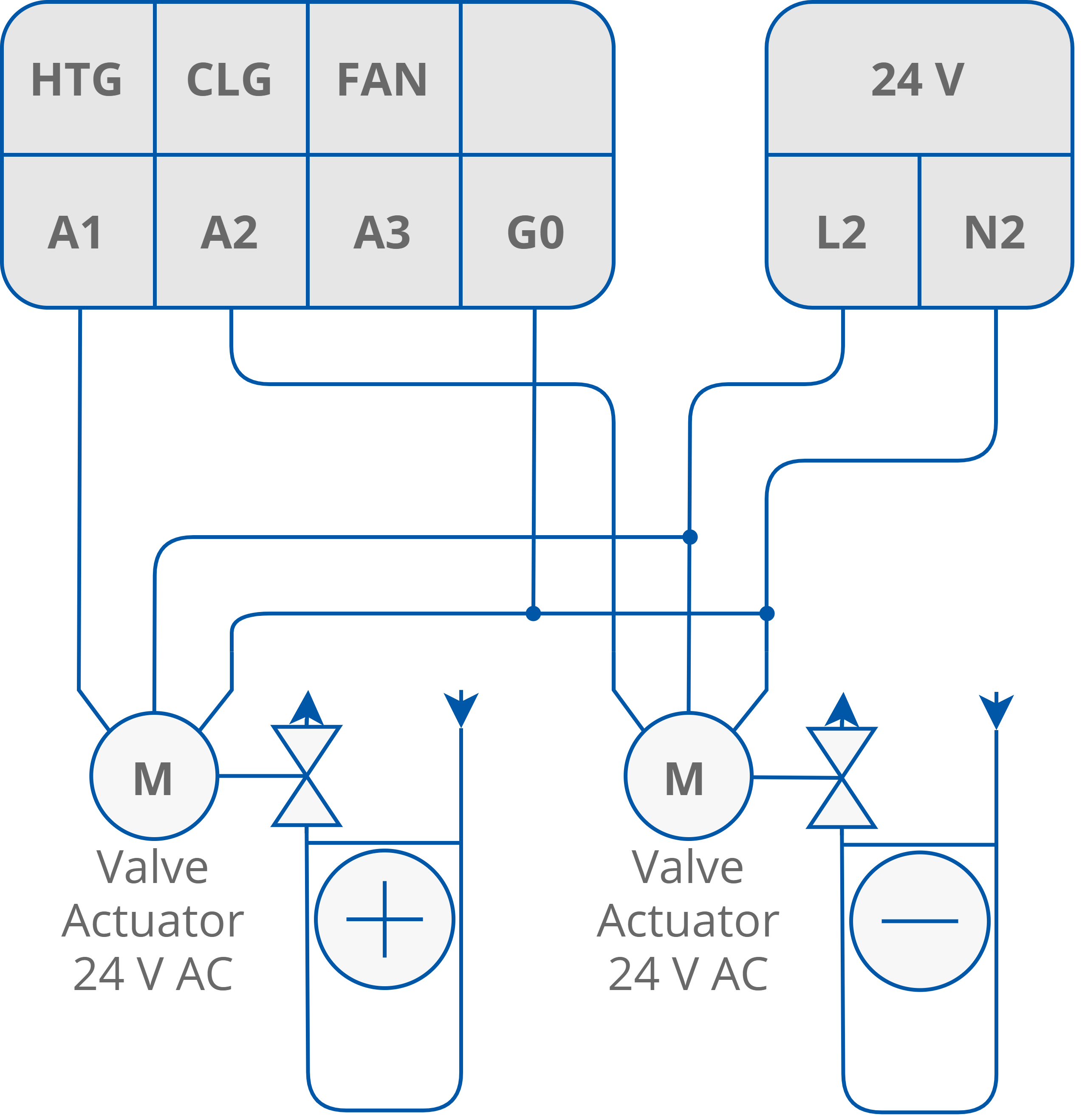
Connection of heater/cooler valve actuators in 4-pipe mode with analog signals 0-10 V DC
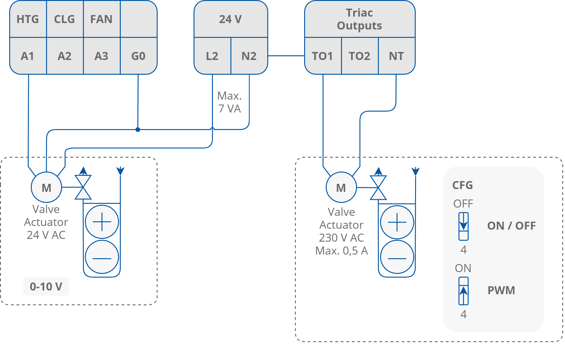
The FCU controller can work with thermal valves actuators. For this option, the FCU controller is equipped with 2 built-in triac outputs. The triac outputs can work in digital (open/close) or PWM mode, selected by the CFG DIP switch number 4. Depending on the hardware version, the FCU controller can work with 230 V AC thermal valve actuators (iSMA-B-FCU-HH) or with 24 V AC thermal valve actuators (iSMA-B-FCU-HL and iSMA-B-FCU-LL). In both cases, thermal valve actuators are supplied with power from the FCU controller.
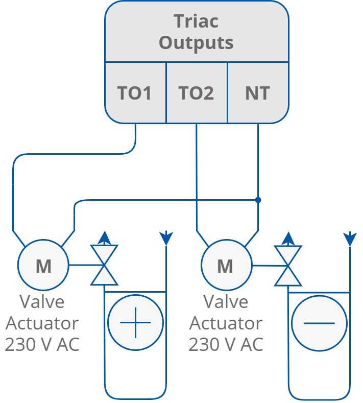
Connection of thermal valve actuator to triac outputs (FCU-HH)
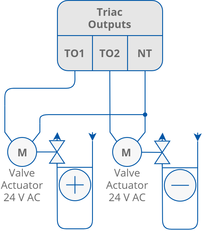
Connection of thermal valve actuator to triac outputs (FCU-HL and FCU-LL)
2-Pipe System
In the 2-pipe system mode, the switch number 1 has to be set to the ON position as presented in the figure below. By default, this mode is OFF.
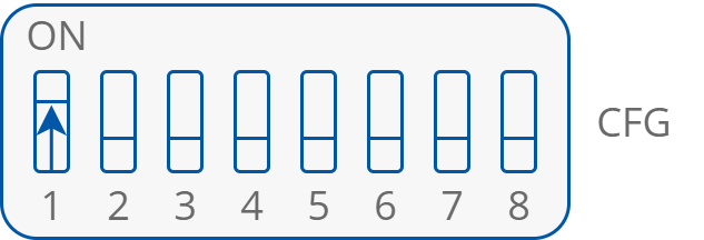
2-pipe DIP switch configuration
Connection of heating/cooling valve actuators in 2-pipe mode