The default application is designed to control 1 of 4 different fan types. The fan type is chosen by the S3 CFG DIP switches number 7 and 8, which is presented in the table below.
|
Name |
Switch Position |
Fan Type |
Default |
|
|---|---|---|---|---|
|
Fan type |
7-off |
8-off |
Analog type |
3-speed type |
|
7-off |
8-on |
1-speed type |
||
|
7-on |
8-off |
2-speed type |
||
|
7-on |
8-on |
3-speed type |
||
Fan type selected with the CFG DIP switch configuration
Source description:
-
room panel: the temperature is sourced from the iSMA-B-LP/Touch Point/FP room panel connected to the FCU controller by RJ12 socket;
-
room sensor: the temperature is sourced from the sensor connected to the S3 special input;
-
air return temperature: the temperature is sourced from the sensor connected to the S1 special input–for more information about the air return temperature, please see section Return Temperature Sensor Control;
-
network temperature: the temperature is sourced from the network variable; this source is dedicated for the slave device in the master-slave working mode.
The connection of supported fan types is shown in figure below.
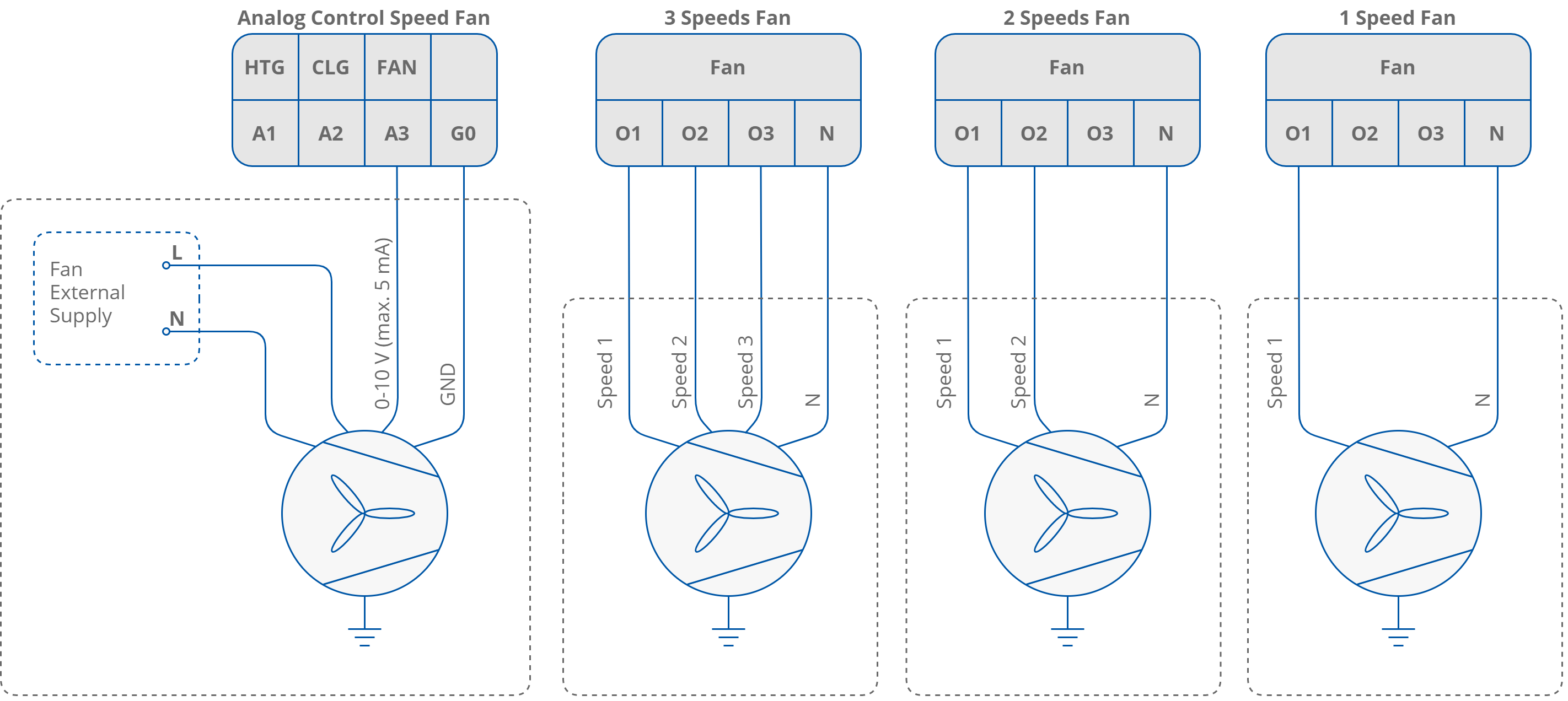
Fan motor connection according to the fan control mode
Note: For the digital fan speed control, the FCU application is equipped with a built-in protecting function to prevent parallel speed switching. There is also 1 second delay between the changes of speed. During the delay, all fan digital outputs are switched off.
Fan Control Algorithm
The FCU application has a built-in fan speed control algorithm. The internal variable Fan Control Value is scaled by the difference between CV and Effective Setpoint. The difference is calculated according to linear conversation, where 100% speed is in the Fan_Scale network parameter. For example: by default, the Fan_Scale network variable value is set to 3, meaning if the difference between the CV and SP is equal or higher than 3°C, the internal parameter Fan_Control_Value is 100% if the difference is half of the Fan_Scale (in this case 1.5°C), the Fan_Control_Value is 50%. The algorithm chart is presented in the figure below.
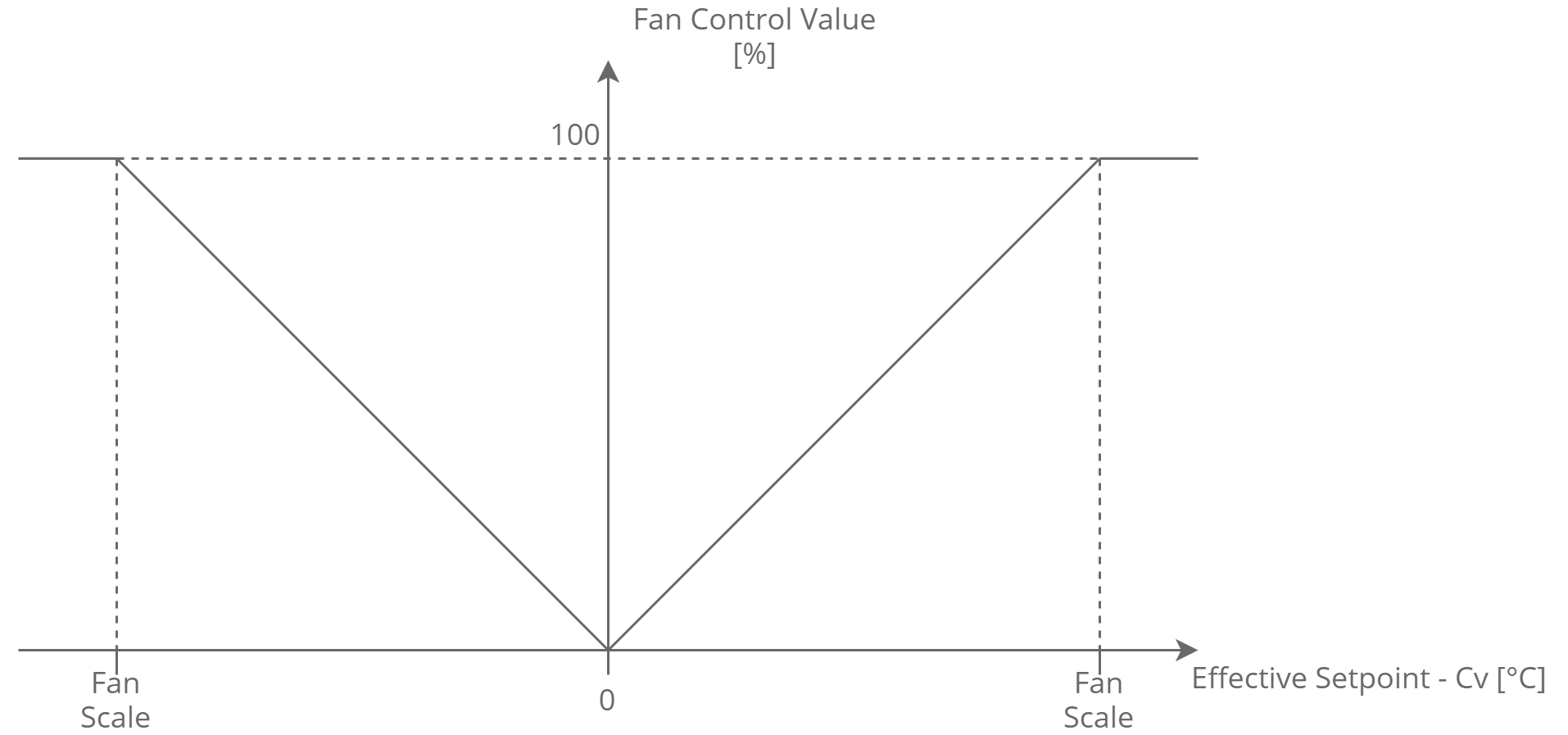
Fan control value conversion chart
The fan can operate in 3 modes: off, manual, auto. These modes can be changed from the room panel, or remotely from the BMS by the Fan_Mode network variable. The current fan status is shown in the read-only network variable, Fan_Status. The Fan_Mode and Fan_Status functions and corresponding values are presented in the table below.
|
Name |
BACnet ID |
Modbus Address |
Value |
Function |
|---|---|---|---|---|
|
Fan Mode |
3 |
103 |
0 |
Off |
|
1 |
Speed 1 (Manual) |
|||
|
2 |
Speed 2 (Manual) |
|||
|
3 |
Speed 3 (Manual) |
|||
|
4 |
Auto |
|||
|
Fan Status |
102 |
202 |
0 |
Off |
|
1 |
Speed 1 (Manual) |
|||
|
2 |
Speed 2 (Manual) |
|||
|
3 |
Speed 3 (Manual) |
|||
|
4 |
Speed 1 (Auto) |
|||
|
5 |
Speed 2 (Auto) |
|||
|
6 |
Speed 3 (Auto) |
Fan Mode and Fan Status variables descriptions
Fan Soft Start
This function is designed for analog fan type control supply by motor driver to support fan motor start. If the fan is starting with small control value, the fan motor might not start or starting process will take a long time. These two situations could make the driver or the fan motor overheat. The Fan Soft Start function overrides the fan control signal for the time defined in the Fan Soft Start Time network variable with the value defined in the Fan Soft Start Value network variable. After the Fan Soft Start Time, the control signal switches to the application fan control signal.
WARNING! For correct values of time and control value, please read the manufacture instructions of motor and driver. Electrical and thermal parameters cannot exceed the values defined by manufacturer.
Fan Off Delay
The Fan Off Delay function was designed to keep the air flow for defined time after the fan switch off signal. The delay time is defined in the Fan Delay Off network variable. This function is dedicated to protect heating or/and cooling devices after switch off.
Fan Analog Type Control Algorithm
For fan analog control, the fan is controlled with A3 analog output signal 0-10 V DC basing on the Fan_Value network variable (0-100%).
In the default application, the Fan_Value network variable is calculated according to the internal variable Fan_Control_Value and Fan Thresholds network parameters. If the fan starts and the Fan_Control_Value is within the range from 0 to Fan_Speed1_Threshold, the fan will be switched off. If the Fan_Control_Value is equal or higher than the Fan_Speed1_Threshold, the fan is switched on and starts working according to the Fan_Control_Value or according to the Soft Start algorithm. The fan will be switched off if the Fan_Value drops below the Fan_Off_Threshold.
The fan control algorithm has a built-in function, which keeps fan running with the Fan_Speed1_Threshold network variable value, when there is no fan demand. This function works only in the occupied mode and has 2 separate network parameters, for cooling–Fan_Cooling_Occupied_Active, and for heating–Fan_Heating_Occupied_Active. The fan working algorithm is presented in the figure below.
The value of the Fan_Value network variable, depending on the Fan_Control_Value and Fan_Off_Threshold, is presented in the figure below.
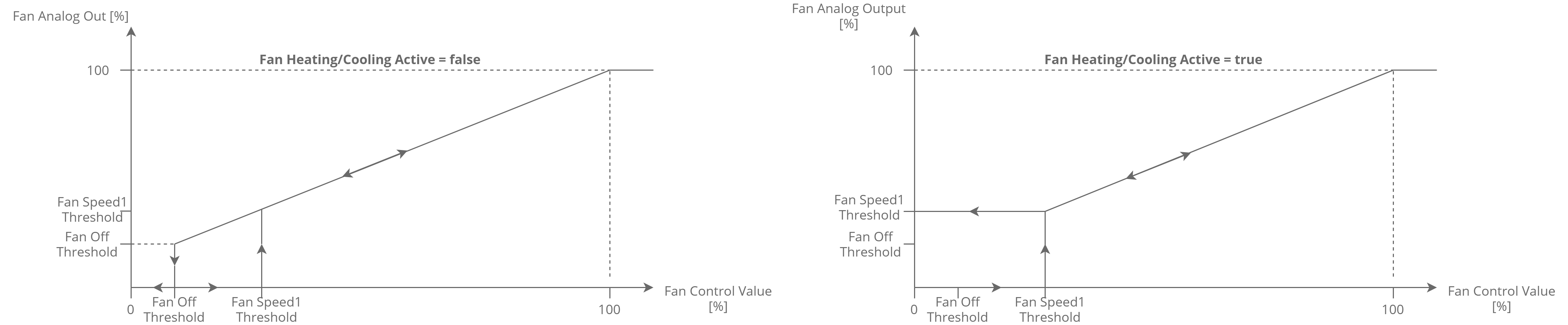
Fan analog type control algorithm
Fan 1-Speed Type Control Algorithm
In the 1-speed fan control mechanism, the fan is controlled by O1 digital output only, basing on the Fan_Value network parameter (0-off; 1-speed 1).
In the default application, the Fan_Value network variable is calculated according to internal variable Fan_Control_Value and Threshold function defined by 2 network parameters:
-
Fan Off Threshold, and
-
Fan Speed 1 Threshold.
The fan control algorithm has a built-in function, which keeps the fan running with low value if there is no fan demand. This function works only in the occupied mode and has 2 separate network parameters, for cooling–Fan_Cooling_Occupied_Active, and for heating–Fan_Heating_Occupied_Active. The fan working algorithm is presented in the figure below.
Fan 1-speed type control algorithm
Fan 2-Speed Type Control Algorithm
In the 2-speed fan control mechanism, the fan is controlled with digital outputs, O1 and O2, basing on the Fan_Value network variable (0–off; 1–speed 1; 2–speed 2).
In default application, Fan_Value network variable is calculated according to internal variable Fan_Control_Value and Threshold function defined by 3 network parameters:
-
Fan Off Threshold;
-
Fan Speed 1 Threshold;
-
Fan Speed 2 Threshold.
The fan control algorithm has a built-in function, which keeps the fan running with low value, if there is no fan demand. This function works only in the occupied mode and has 2 separate network parameters, for cooling–Fan_Cooling_Occupied_Active, and for heating–Fan_Heating_Occupied_Active. The fan working algorithm is presented in the figure below.
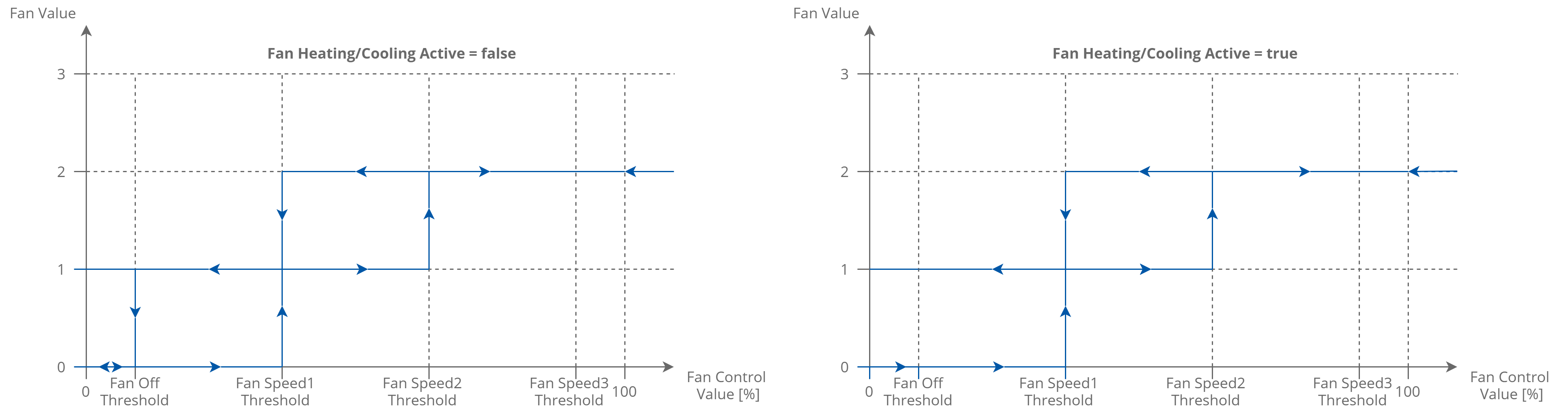
Fan 2-speed type control algorithm
Fan 3-Speed Type Control Algorithm
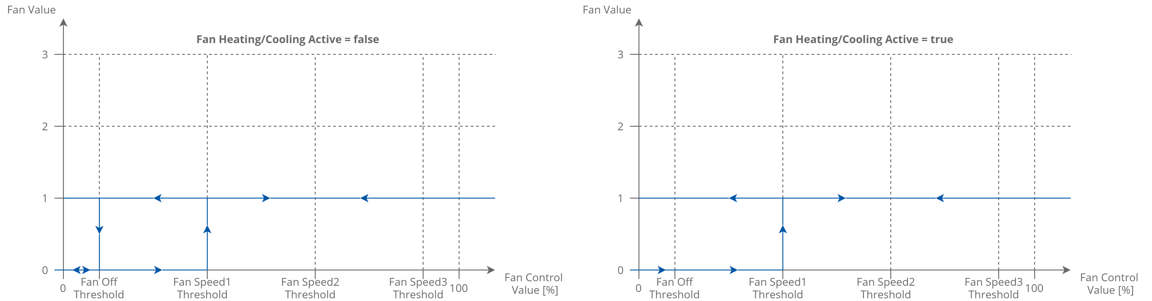
In the 3-speed fan control mechanism, the fan is controlled by O1, O2, and O3 digital outputs, basing on the Fan_Value network variable (0–off; 1–speed 1; 2–speed 2; 3–speed 3).
In the default application, the Fan_Value network variable is calculated according to internal variable Fan_Control_Value and Threshold function defined by 4 network parameters:
-
Fan Off Threshold;
-
Fan Speed 1 Threshold;
-
Fan Speed 2 Threshold;
-
Fan Speed 3 Threshold.
The fan control algorithm has a built-in function, which keeps the fan running with low value if there is no fan demand. This function works only in the occupied mode and has 2 separate network parameters, for cooling–Fan_Cooling_Occupied_Active, and for heating–Fan_Heating_Occupied_Active. The fan operating algorithm is presented in the figure below.
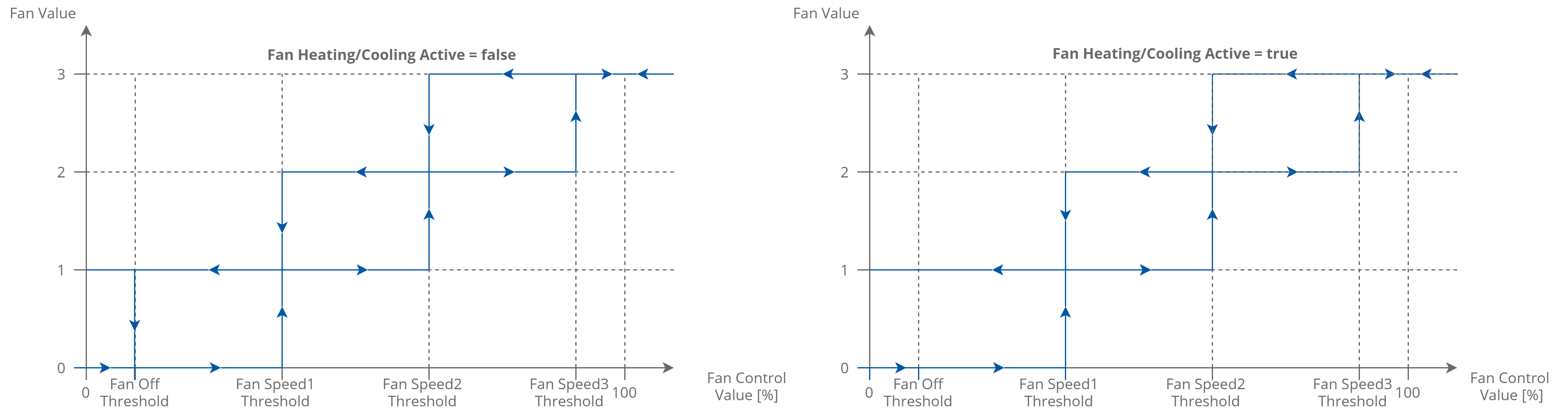
Fan 3-speed type control algorithm