This section describes using all inputs and outputs with default application loaded on iSMA-B-FCU device.
Special Inputs
The iSMA-B-FCU device has four special inputs. In the default application, dedicated temperature sensors and/or potentiometer have to be connected to each input. The figure below presents the way all special inputs are connected.
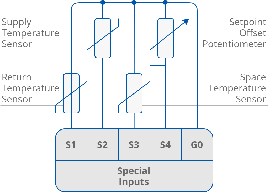
The special inputs connection
|
Name |
Units |
Access |
BACnet BV ID |
BACnet AV ID |
Modbus Coil |
Modbus Register |
Default Value |
|---|---|---|---|---|---|---|---|
|
S1_Return_Temperature |
oC |
RO |
- |
113 |
- |
213 |
- |
|
S2_Supply_Temperature |
oC |
RO |
- |
114 |
- |
214 |
- |
|
S3_Space_Temperature |
oC |
RO |
- |
115 |
- |
215 |
- |
|
S1_Sensor_Type |
N/A |
RW |
- |
43 |
- |
143 |
1 |
|
S2_Sensor_Type |
N/A |
RW |
- |
44 |
- |
144 |
1 |
|
S3_Sensor_Type |
N/A |
RW |
- |
45 |
- |
145 |
1 |
Special inputs network parameters
Digital Inputs
The iSMA-B-FCU device is equipped with four digital inputs. The way of connecting all signals to the inputs is presented in the figure below. Digital inputs O1st O3 can be inverted, depending on the type of sensors connected to the device.
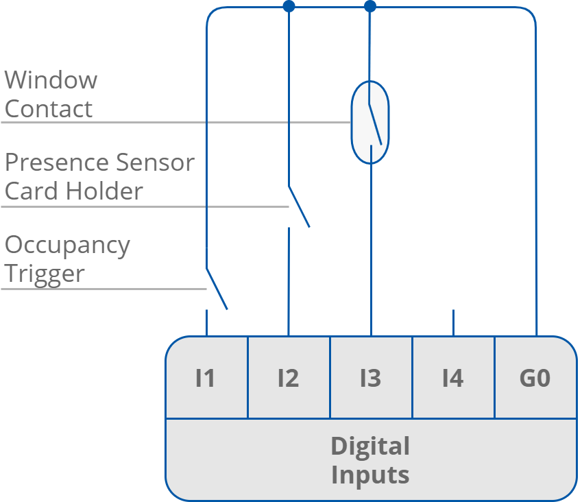
The digital inputs connection
|
Name |
Units |
Access |
BACnet BV ID |
BACnet AV ID |
Modbus Coil |
Modbus Register |
Default Value |
|---|---|---|---|---|---|---|---|
|
I1_Remote_Occupancy_Trigger |
- |
RO |
82 |
- |
1282 |
- |
- |
|
I2_Presence_Sensor_Card_Holder |
- |
RO |
83 |
- |
1283 |
- |
- |
|
I3_Window_Contact |
- |
RO |
84 |
- |
1284 |
- |
- |
|
I1_Remote_Occupancy_Trigger_Invert |
- |
RW |
6 |
- |
1206 |
- |
Off |
|
I2_Presence_Sensor_Card_Holder_Invert |
- |
RW |
7 |
- |
1207 |
- |
Off |
|
I3_Window_Contact_Invert |
- |
RW |
8 |
- |
1208 |
- |
Off |
Digital inputs network parameters
Triac Outputs
The iSMA-B-FCU device has two triac outputs to connect the actuators of heating and cooling valves. Both can work as typical binary outputs (for binary temperature control) or with the PWM. In the PWM mode, the output works in the period when two states are used (low state 0 V and high state 24 V AC or 230 V AC, depending on the hardware version). The periods are defined by the PWM_Heating_Period network variable for the TO1 output and PWM_Cooling_Period network variable for the TO2 output (both are set to 300 seconds by default). The control signal defines the output of high state in working period (in percentage). Depending on the hardware version, triac outputs can work with 230 V AC thermal valve actuators (iSMA-B-FCU-HH) or with 24 V AC thermal valve actuators (iSMA-B-FCU-HL and iSMA-B-FCU-LL).
The way of connecting the actuators to the triac outputs in 4-pipe application is presented in the figures below.
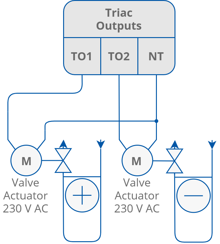
Triac outputs connection
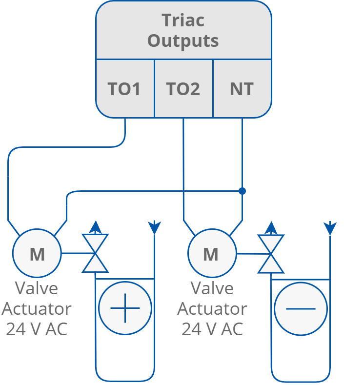
Connection of thermal valve actuators to triac outputs
Note: In case of the iSMA-B_FCU-HH and iSMA-B-FCU-LL devices, actuators connected to each triac output may consume up to 0.5 A. In case of the iSMA-B-FCU-HL device, the sum of power consumption of both triac outputs and 24 V AC output cannot exceed 0.3 A (7 VA):
Imax = 0.3A = ITO1 + ITO2 + I24VOut.
|
Name |
Units |
Access |
BACnet BV ID |
BACnet AV ID |
Modbus Coil |
Modbus Register |
Default Value |
|---|---|---|---|---|---|---|---|
|
Heating_Valve |
% |
RO |
- |
110 |
- |
210 |
N/A |
|
Cooling_Valve |
% |
RO |
- |
111 |
- |
211 |
N/A |
|
PWM_Heating_Period |
s |
RW |
- |
15 |
- |
115 |
300 |
|
PWM_Cooling_Period |
s |
RW |
- |
16 |
- |
116 |
300 |
Traic output network parameters
Digital Outputs
Fan Outputs
The iSMA-B-FCU device is equipped with three relay outputs designed for connecting with the fan. The way of connecting the fan (depending on the number of speeds) is presented in the figure below. These outputs have internal connection to the power supply terminal and are protected by a built-in 6 A fuse. The total load for digital outputs O1st O3, O5, and triac cannot extend 6 A in both 230 V AC and 24 V AC power supply versions.
Note: In iSMA-B-FCU-HL, the triac outputs are supplied with power by a built-in transformer and a minimal part in power supply is input current.
WARNING! Please note that the inductive load of the relays is limited to 75 VA.
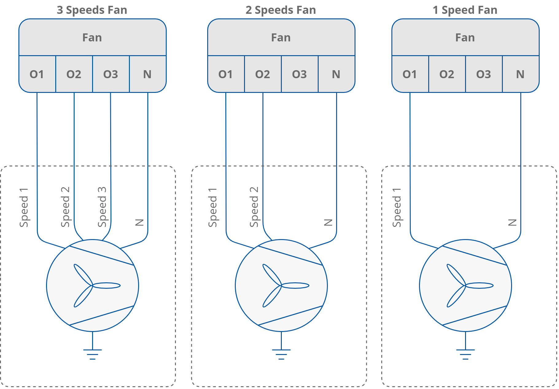
Fan connections
|
Name |
Units |
Access |
BACnet BV ID |
BACnet AV ID |
Modbus Coil |
Modbus Register |
Default Value |
|---|---|---|---|---|---|---|---|
|
Fan Value |
% |
RO |
- |
112 |
- |
212 |
N/A |
|
Fan Type |
N/A |
RO |
- |
103 |
- |
203 |
0 |
Fan Type and Fan Value parameters
Electrical Heater (HTG)
The iSMA-B-FCU device is equipped with a relay output for connecting the electrical heater. This output can be used for 1st or 2nd stage heating, depending on the CFG DIP switch configuration. This output is not internally connected to the power supply, therefore it is necessary to use external supply. Relay current cannot exceed 10 A for resistance load at 250 V AC power supply. The way of connecting the electric heater to O4 HTG is presented in the figure below.
Note: The HTG relay voltage is always limited to 250 V AC, irrespectively of the FCU controller power supply.
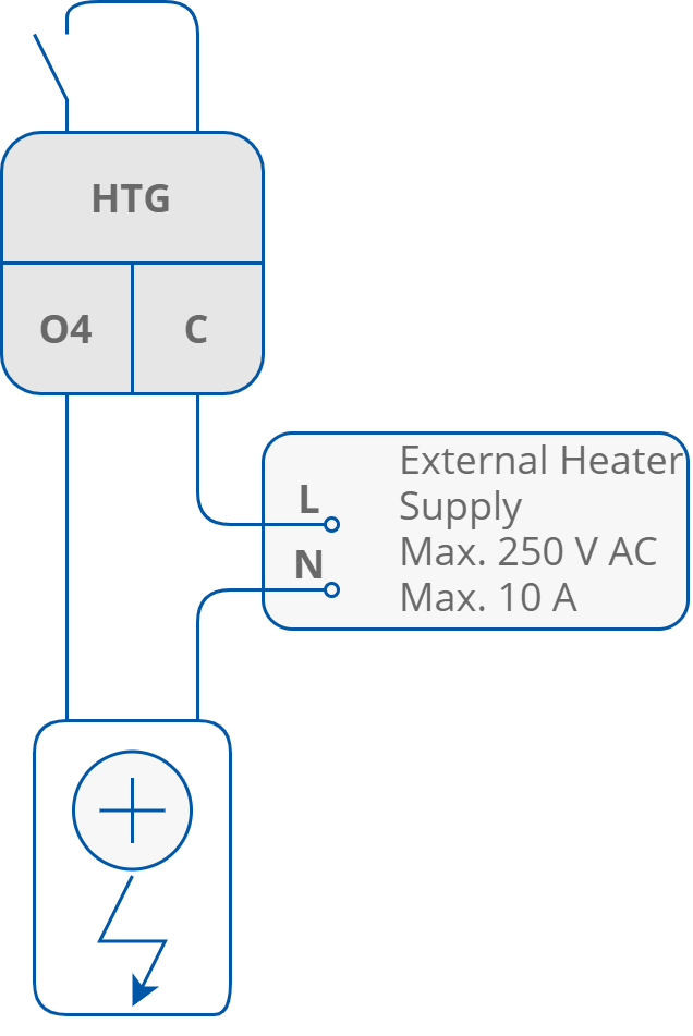
Electrical heater connections
|
Name |
Units |
Access |
BACnet BV ID |
BACnet AV ID |
Modbus Coil |
Modbus Register |
Default Value |
|---|---|---|---|---|---|---|---|
|
Heating_Second_Stage |
- |
RO |
80 |
- |
1280 |
- |
N/A |
|
HTG Relays Enable |
- |
RW |
4 |
- |
1204 |
- |
True |
Network parameters of the O4 HTG digital output
Electrical Cooler (CLG)
The iSMA-B-FCU device is equipped with a relay output for connecting the electrical cooler. This output can be used as 1st or 2nd stage cooling, depending on the CFG DIP switch configuration. The relay output is connected with the power supply internally, therefore it is not necessary to connect an external supply. In the iSMA-B-FCU-HH and iSMA-B-FCU-HL, the output voltage in high state is 230 V AC, whereas in iSMA-B-FCU-LL version the high state output voltage is 24 V AC. In total, the relay current with fan and triac outputs cannot exceed 6 A. The way of connecting the electric cooler to O5 CLG is presented in the figure below.
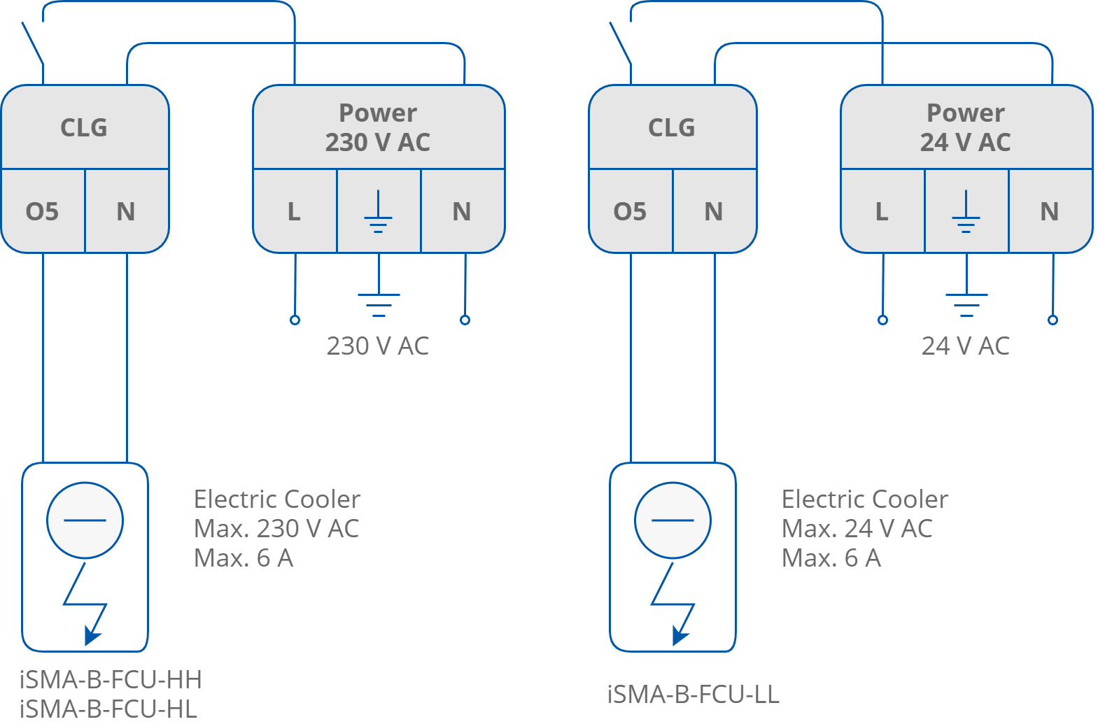
Electrical cooler connection
|
Name |
Units |
Access |
BACnet BV ID |
BACnet AV ID |
Modbus Coil |
Modbus Register |
Default Value |
|---|---|---|---|---|---|---|---|
|
Cooling_Second_Stage |
- |
RO |
81 |
- |
1281 |
- |
N/A |
|
CLG Relays Enable |
- |
RW |
5 |
- |
1205 |
- |
True |
Network parameters of the O5 CLG digital output
Analog Outputs
The iSMA-B-FCU device has 3 analog outputs 0-10 V DC, which can be used for controlling the following fan coil unit devices:
-
A1 (HTG), analog heating valve actuator control;
-
A2 (CLG), analog cooling valve actuator control;
-
A3 (FAN), analog fan speed control.
The way of connecting all analog outputs is presented in the figures below.
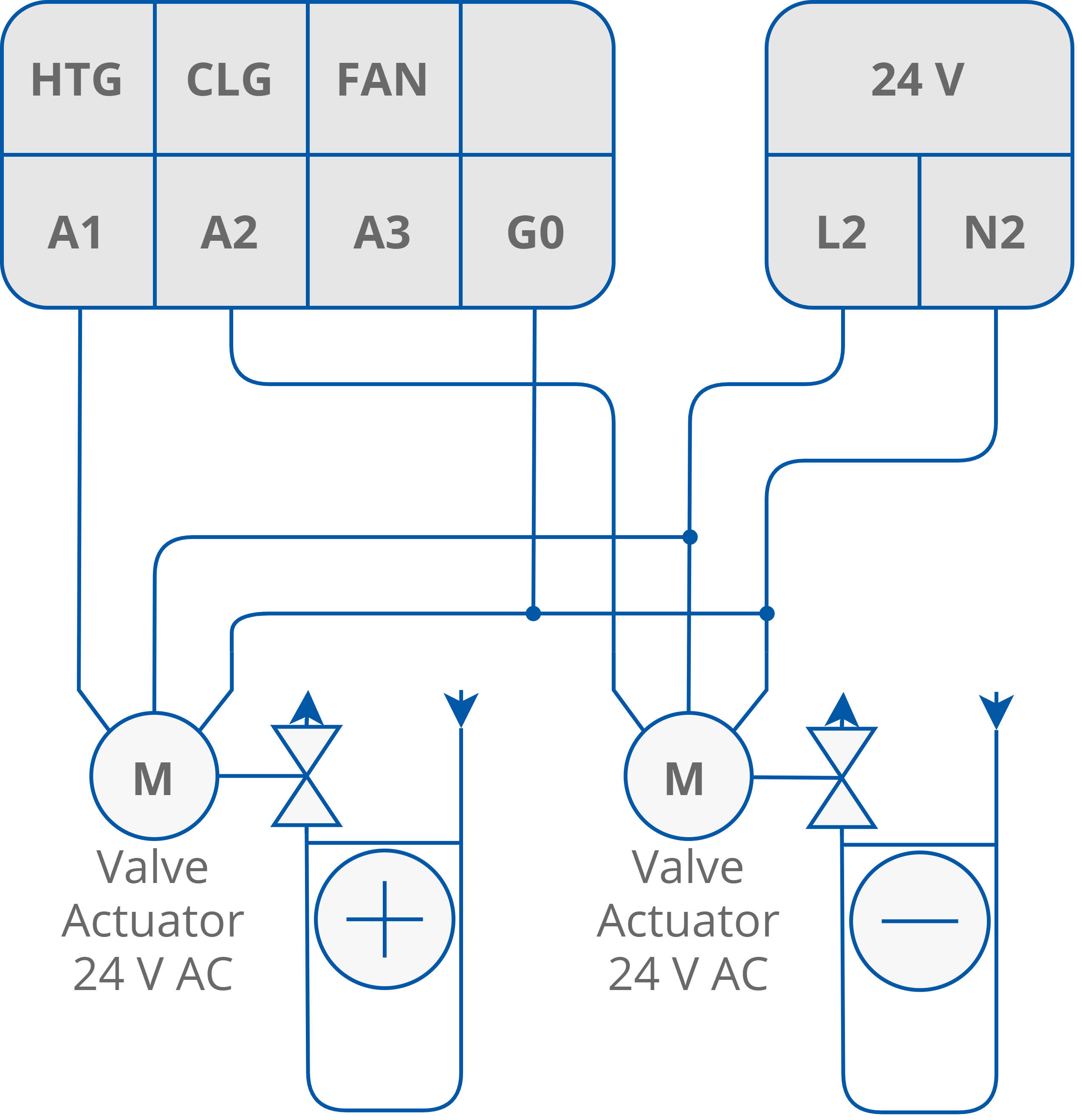
Connection of analog valve actuators
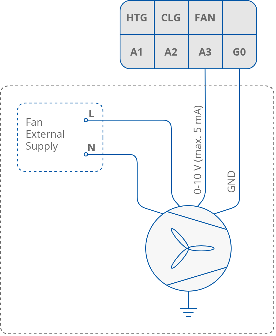
Connection of analog fan control
|
Name |
Units |
Access |
BACnet BV ID |
BACnet AV ID |
Modbus Coil |
Modbus Register |
Default Value |
|---|---|---|---|---|---|---|---|
|
Heating_Valve |
% |
RO |
- |
110 |
- |
210 |
- |
|
Cooling_Valve |
% |
RO |
- |
111 |
- |
211 |
- |
|
Fan Value |
% |
RO |
- |
112 |
- |
212 |
- |
Analog outputs status network parameters