Controller Overview
This section describes steps required to properly configure the controller with the universal FCU application. For further information, please see the RAC18-IP Software and Hardware user manuals.
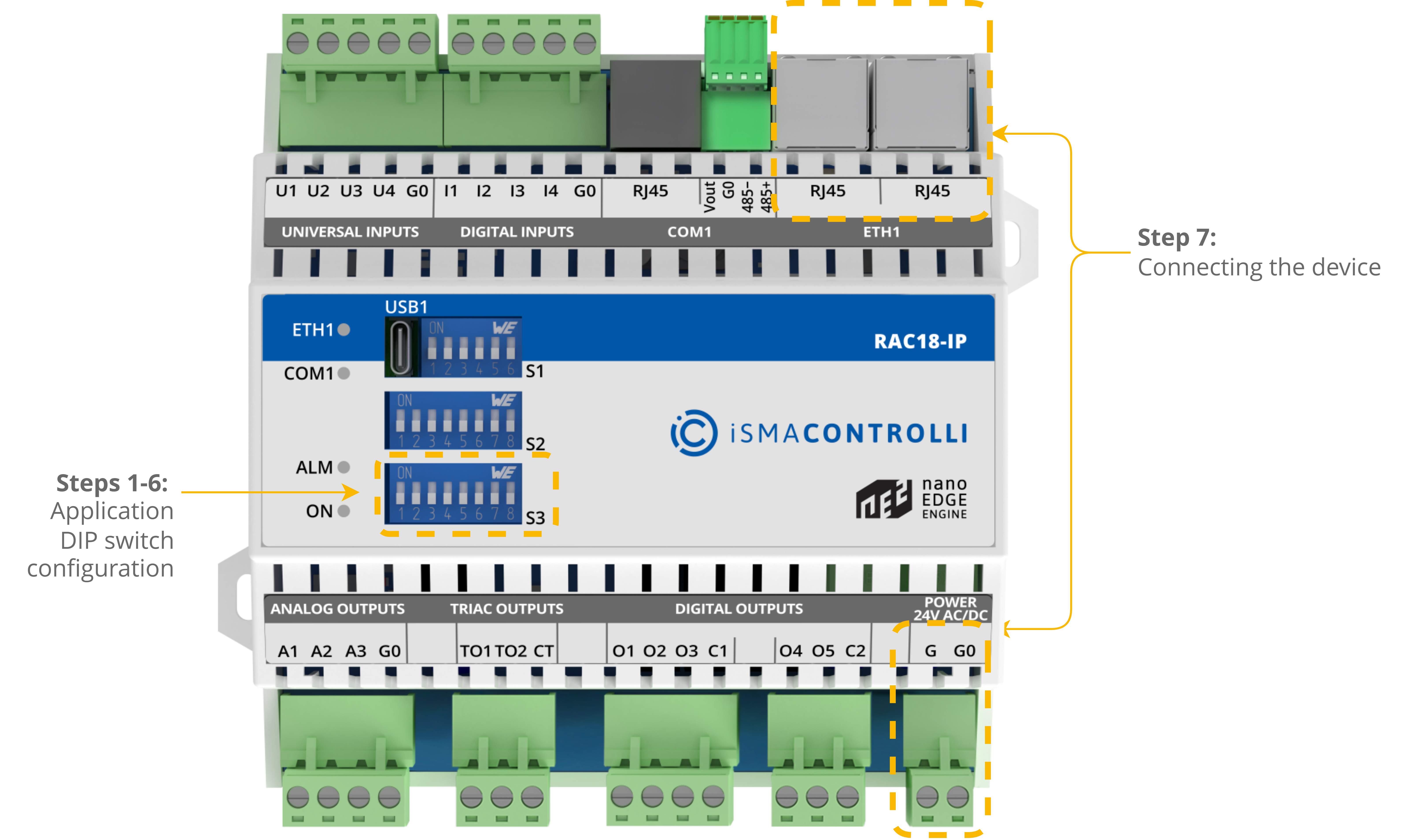
The S3 DIP switch is responsible for configuring the application.
The configuration of the RAC18-IP controller with the universal FCU application is described step by step in the section of the manual:
Step 1: selecting the FCU pipe type;
Step 2: selecting 1 or 2 stages of heating;
Step 3: selecting 1 or 2 stages of cooling;
Step 4: selecting the type of control the FCU valves require, and heating and cooling actuators connection details;
Step 5: selecting the temperature control value source;
Step 6: selecting the type of fan used within the project.
Steps 1-6 describe configuration of the S3 DIP switch. Their overview with default positioning is presented in the table below.
|
No. |
Name |
On |
Off |
Default |
|
|---|---|---|---|---|---|
|
1 |
Pipe mode |
2-pipe |
4-pipe |
4-pipe |
|
|
2 |
Heating 2nd stage |
Enable |
Disable |
Disable |
|
|
3 |
Cooling 2nd stage |
Enable |
Disable |
Disable |
|
|
4 |
Heating/cooling control mode |
Analog |
Digital |
Digital |
|
The S3 DIP switch configuration
WARNING! Before attempting to configure the controller, make sure to have acquainted with all the required documentation, or have a good knowledge of the fan coil unit application–this will make configuration of the controller easy and trouble-free.