Introduction
MAC36 are compact Master Application Controllers powered by the Niagara Framework, with various types of 36 onboard inputs and outputs. Using the specific local I/O set of 16 UI, 8 AO, 4 DI, and 8 DO allows to employ the devices in different applications. MAC36 controllers provide control, data logging, alarming, scheduling, integration, and visualization.
The range of MAC36 controllers consists of:
-
iSMA-B-MAC36NL;
-
iSMA-B-MAC36PRO.
Revision History
|
Rev. |
Date |
Description |
|---|---|---|
|
1.6 |
23 Feb 2024 |
BTL certification for MAC36NL controllers |
|
1.5 |
10 Nov 2023 |
MAC36PRO references |
|
1.4 |
25 May 2022 |
|
|
1.3 |
16 Dec 2020 |
Document corrections |
|
1.2 |
31 Mar 2020 |
Rotary and DIP switches support added |
|
1.1 |
31 Oct 2019 |
|
|
1.0 |
1 Oct 2018 |
First edition |
Revision history
LocalIO Hardware Specification
MAC36 controllers have various types of 36 onboard inputs and outputs. Using the specific local I/O set of 16 UI, 8 AO, 4 DI, and 8 DO allows to employ the devices in different applications.
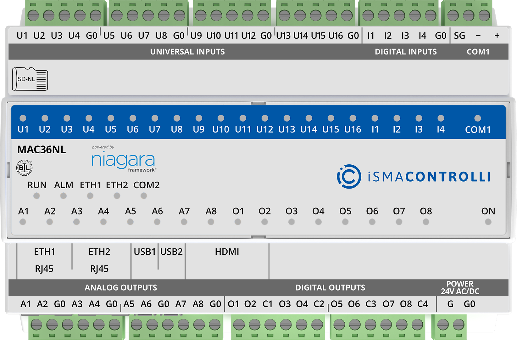
MAC36NL controller
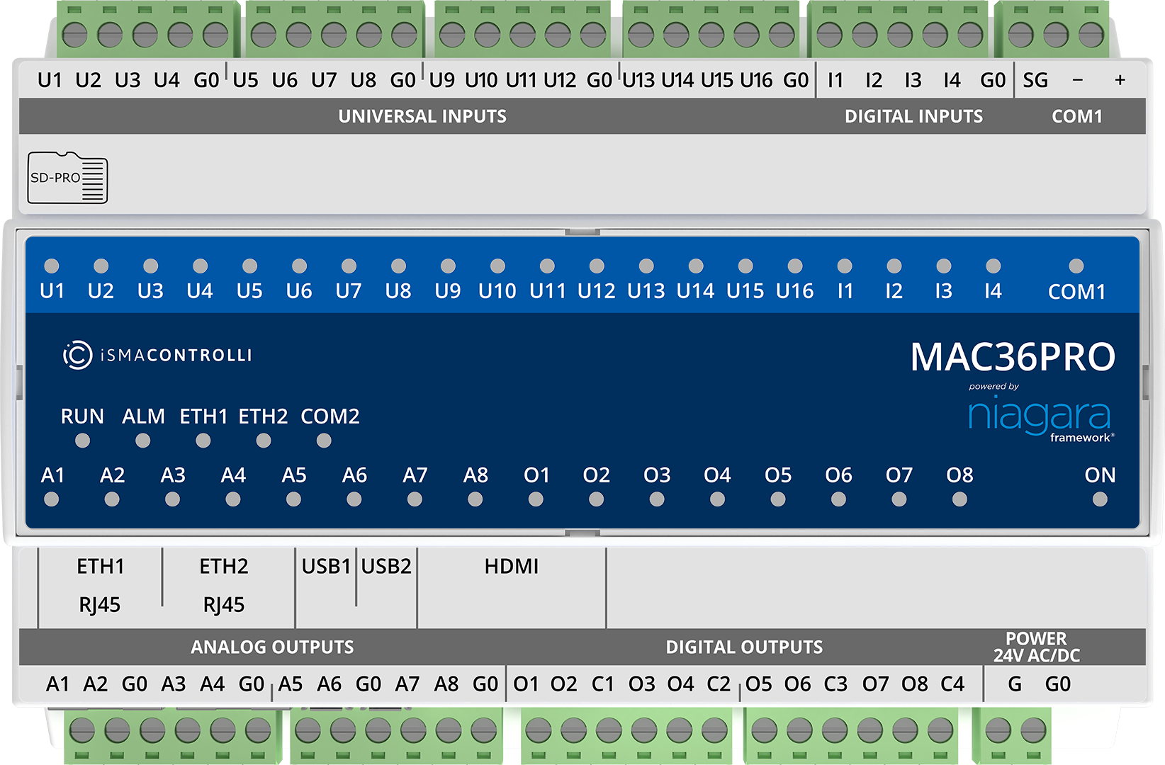
MAC36PRO controller
Terminals and Internal Connection Diagram
MAC36 controllers are supplied by 24 V AC/DC. The power supply block is separated. The grounding pin, located next to power supply terminals, must be connected to the ground.
The device has 36 local I/O on board:
-
8 digital outputs (8 DO), relay output with max. load 3 A at 230 V AC/30 V DC;
-
8 analog outputs (8 AO), voltage output 0-10 V DC maximum load up to 20 mA;
-
16 universal inputs (16 UI), temperature, voltage, current, resistive, or dry contact;
-
4 digital inputs (4 DI), dry contact inputs or fast counter up to 100 Hz.
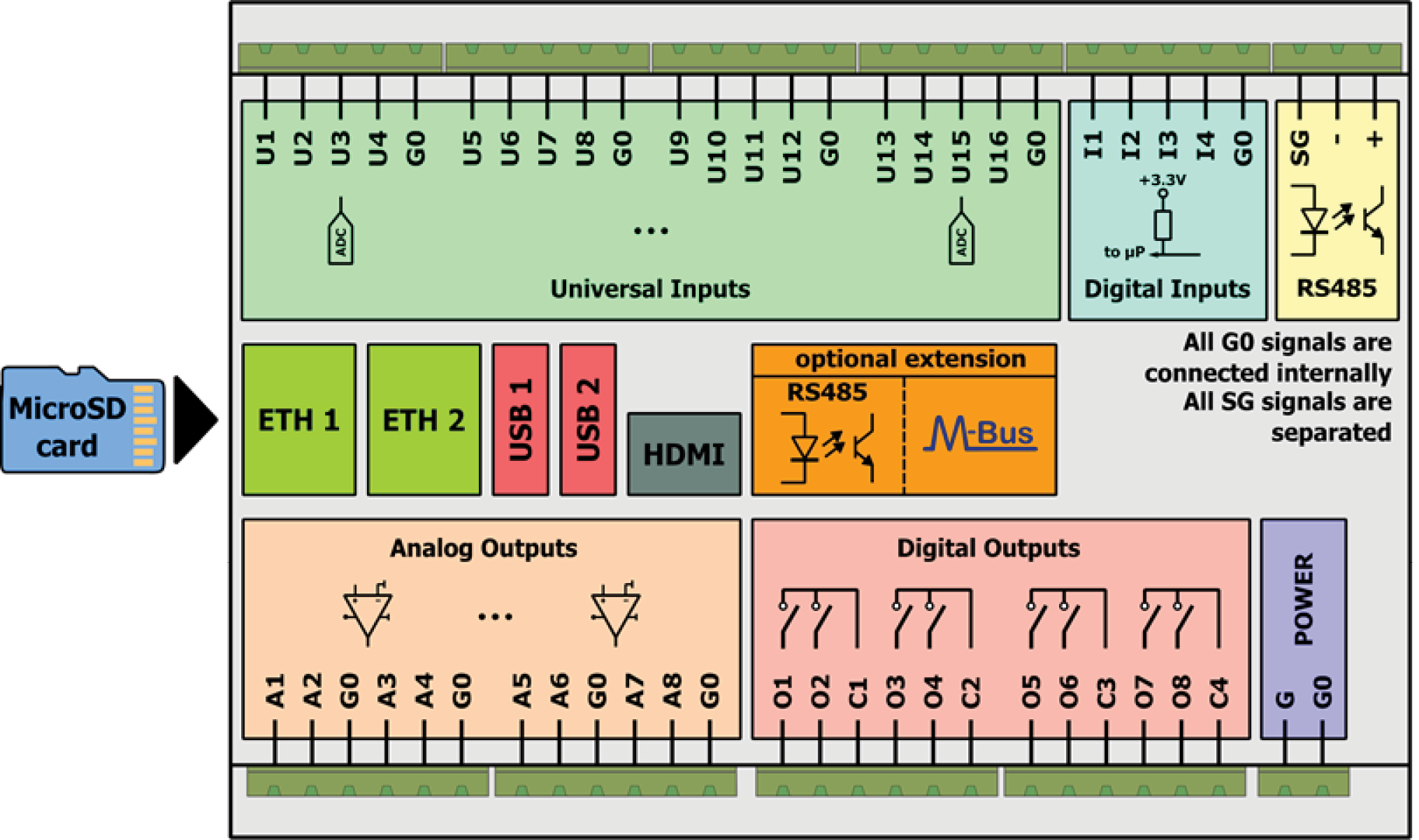
Block diagram
LED Indicators
The device is equipped with LEDs for quick status checking and diagnostics:
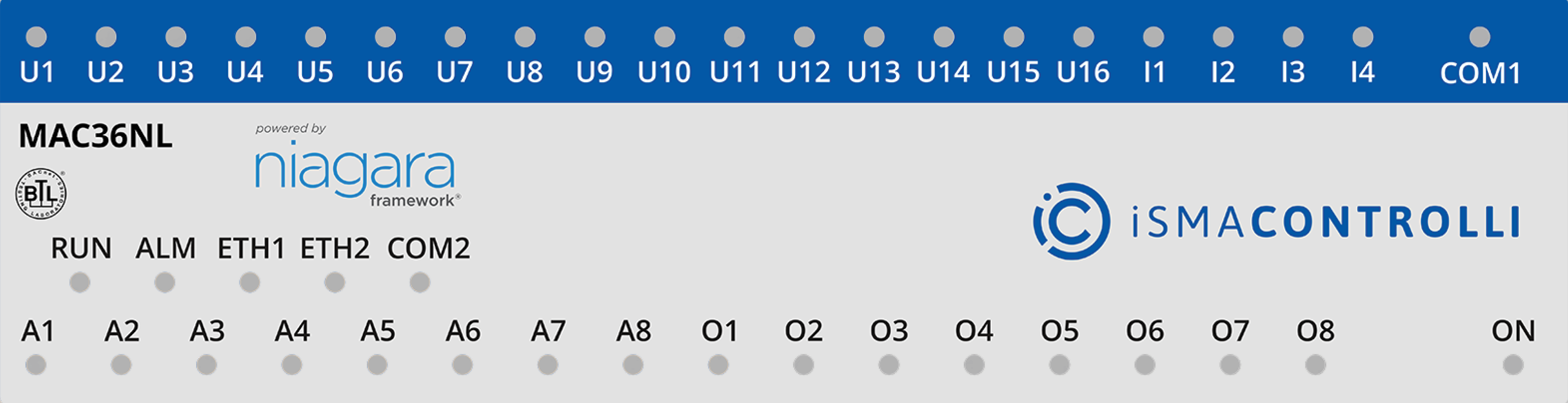
LEDs of a front panel of the iSMA-B-MAC36NL-RS
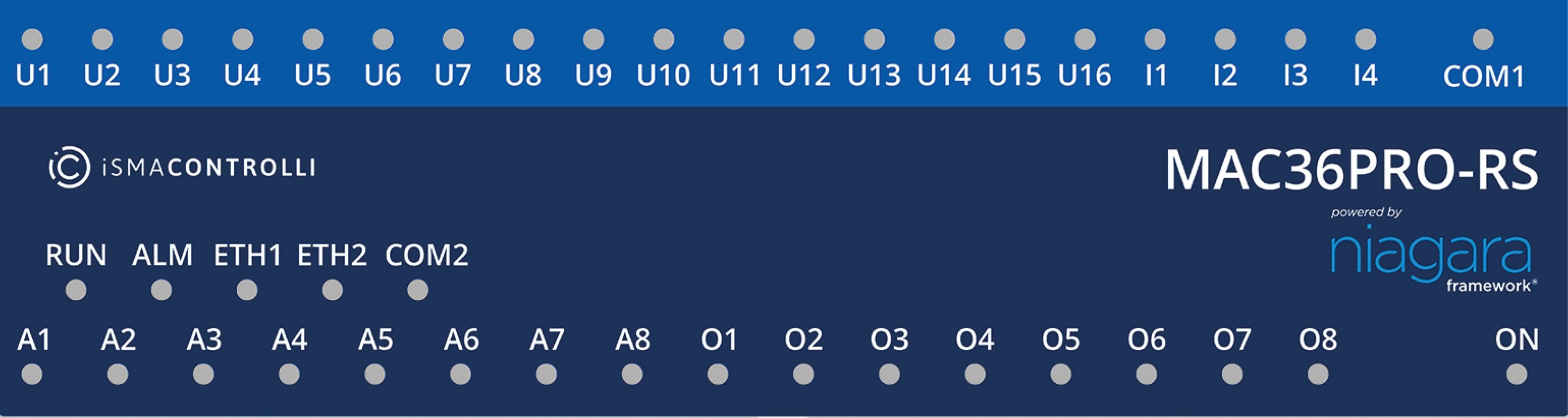
LEDs of a front panel of the iSMA-B-MAC36PRO-RS
-
The universal inputs LEDs U1-U16 indicate the statuses of the universal inputs. If the LED is ON, the resistance value connected to the input is lower than the switching threshold value (dry contact input is active).
Note: The LED also lights up if the voltage connected to the input has a very low potential.
-
The digital inputs LEDs I1-I4 indicate the statuses of the digital inputs. If the LED is ON, the input is active (resistance value connected to the input is lower than the switching threshold value).
-
The analog outputs LEDs A1-A8 indicate the statuses of the analog outputs. If the LED is ON, the output voltage or PWM factor is different than 0.
-
The digital outputs LEDs O1-O8 indicate the statuses of the digital outputs. If the LED is ON, the output is active (closed circuit).