Adding Links
A link is a way of exchanging data between components. It connects components between which the data are transferred. The link identifies, which parameter is taken into account on both sides of the connection. This allows to show the data flow direction, i.e., where a specific parameter is read and where it is saved.
The Wire Sheet view shows the link as a line connecting two components. The Workspace Tree window and the Property Sheet view do not show information about existing links at all.
Views designed to check links for a specific component are the Wire Sheet view and the Links tab in the Object Properties window.
Reference Links
Linking within applications, built with the nano EDGE ENGINE, may be performed twofold: using a standard linking method or using a special Reference link designed specifically to connect Data Point class components (in the Applications container) with network point class components (in the Networks container):
-
The Reference link is a special compound link designed to connect Data Points with network points. The Reference link is created between special Reference slots and transfers values along with the component's status. Alternatively, it may transfer values between Data Points and network points at the same time returning status from network points to Data Points, or it may return values from network points to Data Points.
-
The standard linking method involves simple creating links between the input and output slots; a standard link transfers a value between the connected slots. Standard linking may be applied between all four containers of the nano EDGE ENGINE device structure.
The Reference link is unique for the nano EDGE ENGINE solution, and it is a recommended method to be used in application building as it offers an advantage of transferring the status information between components.
Worth to Notice:
By default, not all slots of a particular component are always visible in the Wire Sheet view. The hidden slots are not displayed in the component default view. A hidden slot becomes visible once it is an end slot to a link. The link to hidden slot may be created using the linking dialog window.
Links in the iC Tool are created in two ways:
-
using the Link Mark and Link From options from the context menu: the Link Mark option selects the source component, and the Link From option selects the target component. The context menu with the Link Mark and Link From options may be opened in the Workspace Tree, Wire Sheet, and Property Sheet;
-
graphically: drawing a line from the source component to the target component. The link may be created graphically in the Wire Sheet. In order to create link graphically, click on the source slot, and drag the line to the target slot. The iC Tool automatically highlights the fitting target slots. As the Wire Sheet displays limited number of slots in the component, drawing a line to the empty row opens a dialog window with the list of all slots to select the target slot.
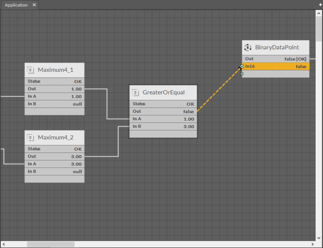
Creating links graphically
A dialog window shows the selected output slot (in the left column) and input slots available to select (in the right column). The available input slots are highlighted in the right column. Selecting the input slot has to be confirmed by pressing Ok.
Creating a link, regardless of a method used, is directly saved to the controller.
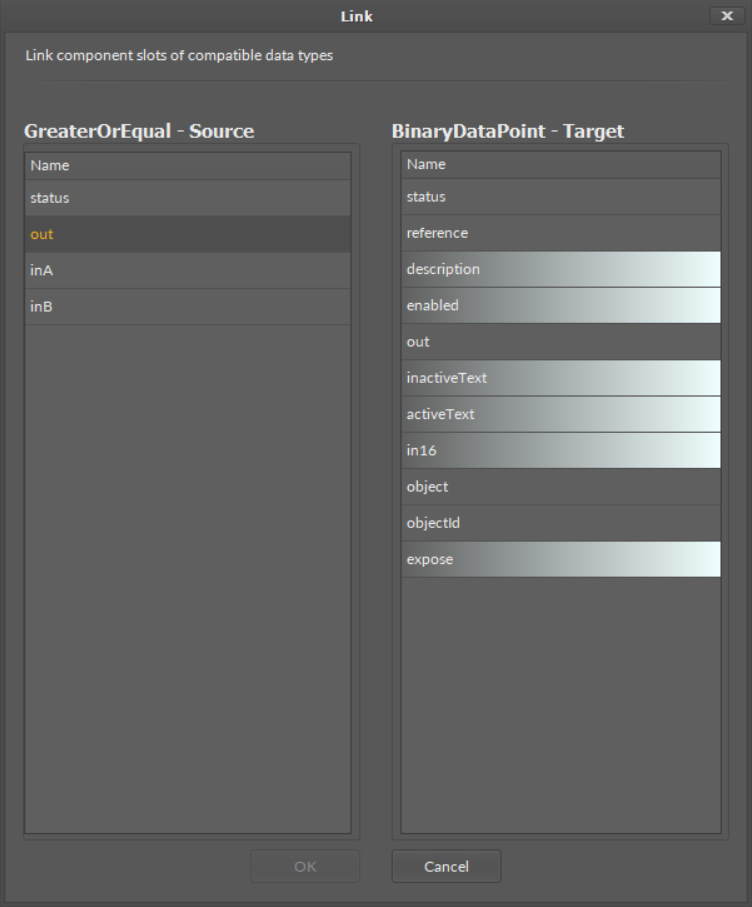
A linking dialog window
Removing Links
A link in the Wire Sheet view can be removed after selecting it and pressing Delete key or choosing a Delete link(s) option from the context menu. If necessary, the remaining links will be automatically redrawn to use the space remaining after the removed one.