
Kits
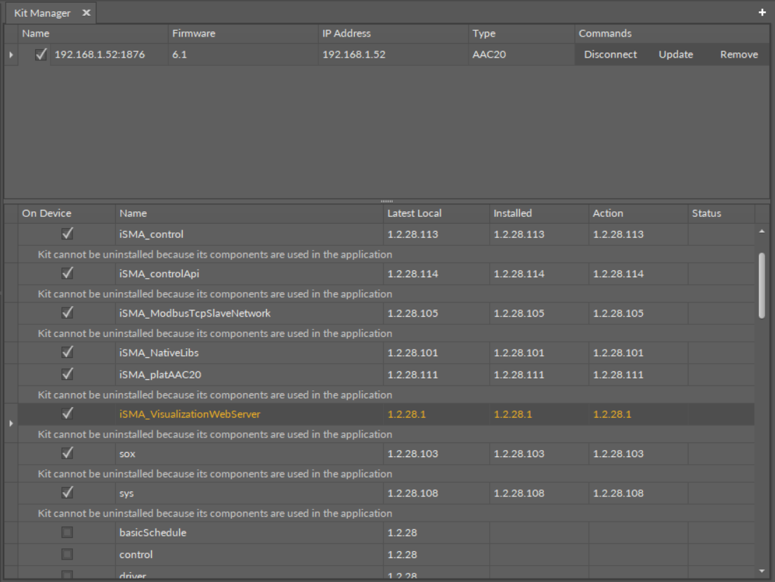
To run the visualization web server, the following kits need to be installed on the controller using the Kit Manager:
iSMA_ModbusTcpSlaveNetwork;
iSMA_VisualizationWebServer.
Web Server Structure of Components in iSMA Tool
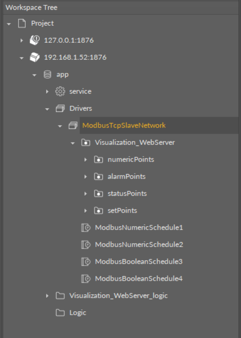
A proper structure of components for the visualization web server to operate adequately is the following:
Demo application vs preexisting user application
The above structure is by default implemented in a demo application, however, the visualization web server can work with a preexisting user application. For this purpose, the components structure must sustained–points (NumericValue or BooleanValue) and schedules components must be located under the ModbusTcpSlaveNetwork component.
In the demo application, the schedules components are automatically linked with the schedules in the Visualization_WebServer_Logic folder. In case of preexisting user application, the links have to be made manually.
Either in the demo or user application, the points have to be linked to source components or have values entered manually. In the demo application, points are grouped into folders, but this is not necessary for the visualization web server to operate properly.
The easiest way to start working with the preexisting user application is to upload a demo application (app.sax) in the AAC20 Simulator, copy the components structure to the destination device, and then create necessary links to the user application.
- ModbusTcpSlaveNetwork: located in the Drivers folder, contains predefined, already addressed, components for the Modbus TCP slave network communication;
- Points (NumericValue or BooleanValue from the iSMA_ModbusTcpSlaveNetwork kit): components representing variables visible on visualization web server page and are responsible for a correct communication;
- Schedules: (ModbusNumericSchedule or ModbusBooleanSchedule from the isma_VisualizationWebServer kit): components for schedules control.
Note: In the demo application, components are sorted and grouped into folders responsible for each editable container on the web page, similar as organized in the Visualization_configurator.xlsm sheets. They also have preconfigured Modbus addresses. If added manually, the points have to be located under the ModbusTcpSlaveNetwork component, and it is crucial to have their Modbus addresses kept compliant with those defined in the Visualization configurator (the Excel file).
The ModbusNumericSchedule and ModbusBooleanSchedule components have the following slots:
Status: the current status of the component;
Fault Cause: indicates the fault cause of the component;
Description: an additional detailed information about a component that may be freely described by the user;
Enable: enables or disables the component;
Starting Address: a number of a first Modbus address used by the schedule;
Number of Events: allows to set a number of daily events in the schedule (the default and maximum value is 8);
Note: Please note that if the number of events in a day is changed and set to less than 8, this change will be automatically read by the visualization web server, and it will not be possible to add more events in the web server view.
Last Address: shows a number of the last Modbus address used by the schedule; the number of used registers depends on the Number of Events slots and the type of the schedule, and is calculated according to the formula:
ModbusNumericSchedule: 4 + (2 * 7 * Number Of Events);
ModbusBooleanSchedule: 1 + (7 * Number Of Events);
Note: The configuration file allows to modify addresses set by default.
Registers in the visualization web server
The visualization web server is designed to accept Modbus addresses from a range of 1000-2999. This range is applicable both to points and schedules.
- Decimal Places (only ModbusNumericSchedule): allows to set a number of decimal places for values displayed on the schedule;
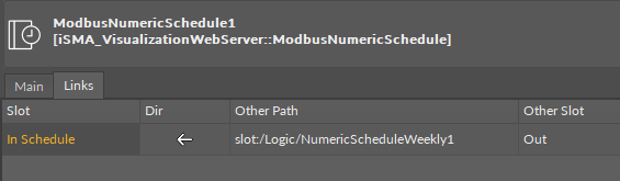
In Schedule: the slot is used to create a link from the schedule's Out slot, and then displays a current value of the linked schedule.
Note: In the demo application, there are two ModbusNumericSchedule and two ModbusBooleanSchedule components directly in the ModbusTcpSlaveNetwork component. They are linked with the schedule components in the logic folder.
Logic
In the demo application, the Visualization_WebServer_logic folder contains four schedule components from the isma_ControlApi kit, which are responsible for schedules in the application and are already linked with components in the Driver folder.
In case of the user application, it is possible to link the components in the application to respective components in the ModbusTcpSlaveNetwork component.