The RJ12 port connector is located between the SD card and USB slots. The connector provides Modbus bus wires, ground potential G0, and power supply directly connected to G terminal from the power supply connector (the external devices can be powered through the RJ12 connector). A wiring diagram is shown in the figure below.
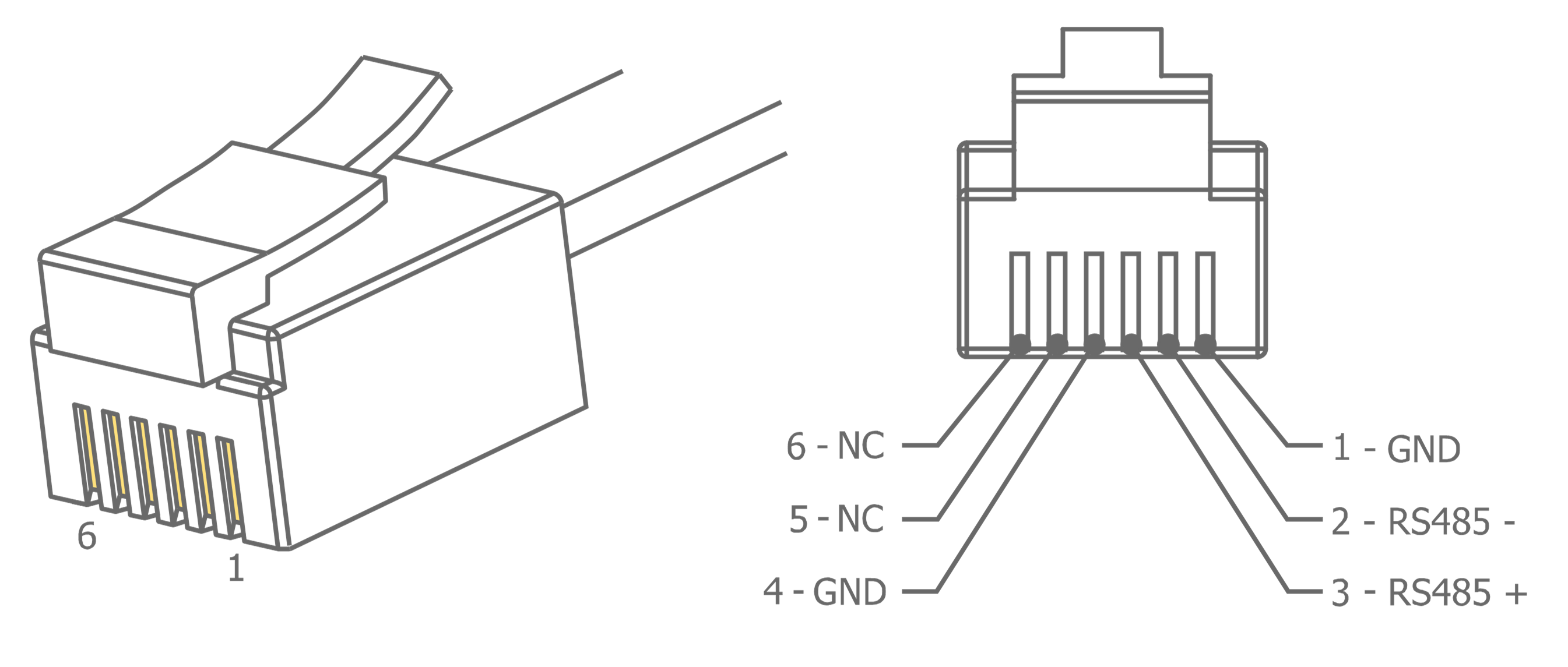
Modbus RJ12 wiring
The RJ12 pins description:
-
Pin1: G0 potential, (SD card side);
-
Pin2: RS485 - (B);
-
Pin3: RS485 + (A);
-
Pin4: G0 potential;
-
Pin5: G potential, directly connected to G terminal in power supply;
-
Pin6: G potential, directly connected to G terminal in power supply (USB side).
Connection of the devices is shown in the figure below.
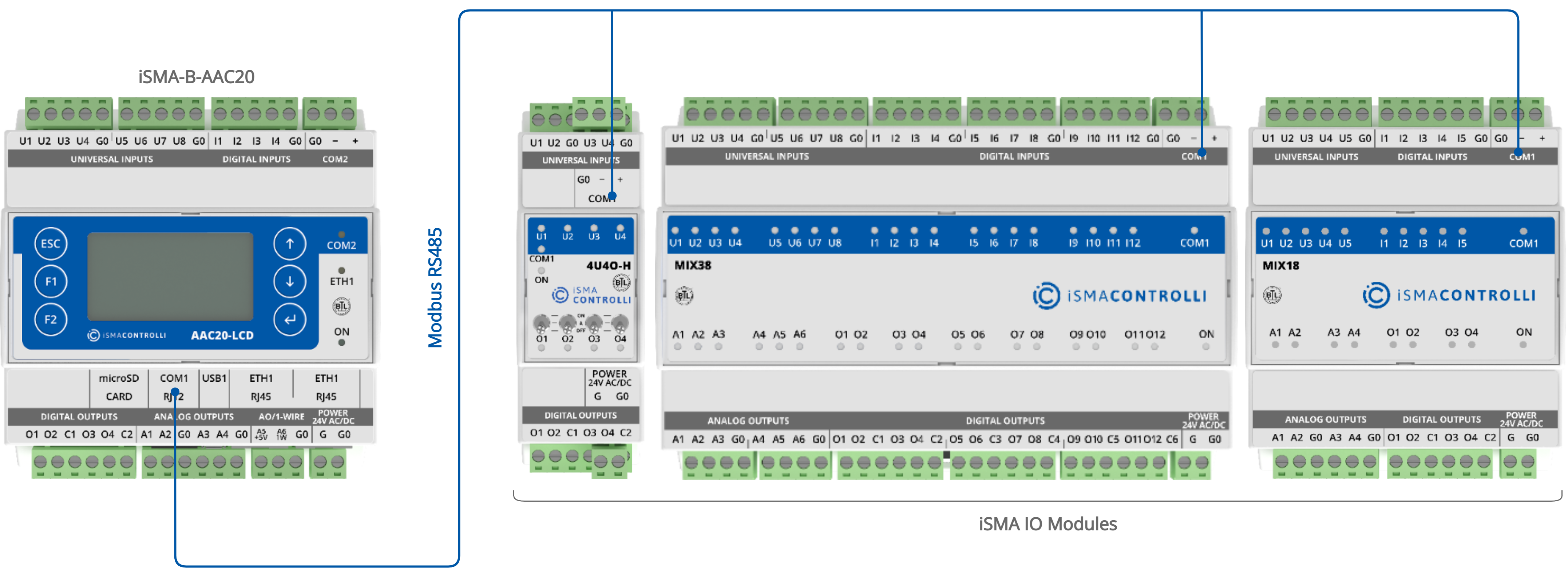
RJ12 to RS485 Modbus connection