Hardware Versions
The iSMA-B-AAC20 controller is an advanced control device for building automation and HVAC systems. The controller is based in the Sedona Virtual Machine (SVM), which allows the user to quickly and easily program the controller in real time. Large number of inputs and outputs allows to integrate with other devices and sensors (AAC20 provides 8 UI, 4 DI, 6 AO, and 4 DO). In addition, to increase the versatility of the controller, it supports many open communications protocols such as BACnet, Modbus, SOX, DALI, M-Bus, 1-Wire. The AAC20 is mounted in a housing adapted for DIN rail mounting or directly on a panel. Separate, easy to remove connectors allow quick wiring without removing the entire device.
The iSMA-B-AAC20 controller comes in six versions depending on native communication protocols and hardware types (basic version and LCD equipped version, see Front Panel for iSMA-B-AAC20 and Front Panel for iSMA-B-AAC20-LCD):
-
iSMA-B-AAC20: basic hardware version, native protocols: Modbus, BACnet, display port, 1-Wire, and
-
iSMA-B-AAC20-LCD: LCD display, native protocols: Modbus, BACnet, display port, 1-Wire:
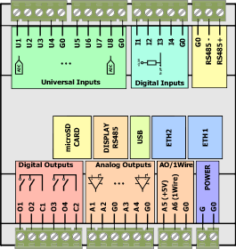
AAC20 basic communication protocols version
-
iSMA-B-AAC20-M: basic hardware version, native protocols: Modbus, BACnet, display port, 1-Wire, M-Bus, and
-
iSMA-B-AAC20-LCD-M: LCD display, native protocols: Modbus, BACnet, display port, 1-Wire, M-Bus:

AAC20 extended M-Bus version
-
iSMA-B-AAC20-D: basic hardware version, native protocols: Modbus, BACnet, display port, 1-Wire, DALI, and
-
iSMA-B-AAC20-LCD-D: LCD display, native protocols: Modbus, BACnet, display port, 1-Wire, DALI:
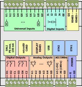
AAC20 extended DALI version
Power Supply
The iSMA-B-AAC20 controllers are designed to work with 24 V AC/DC power supply.
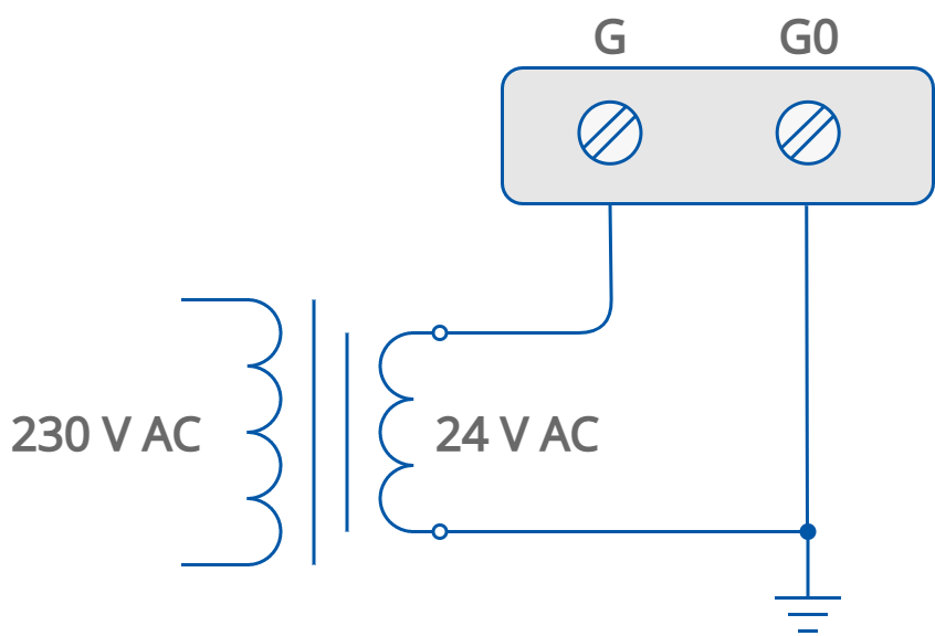
AC power supply connection
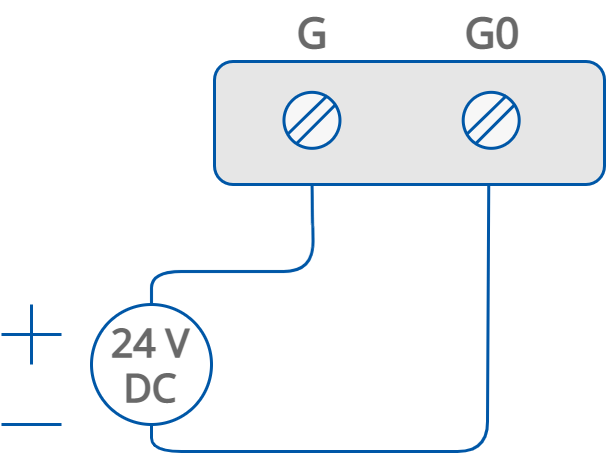
DC power supply connection
Grounding and Shielding
In most cases controllers are installed in enclosures along with other devices, which generate electromagnetic radiation (for example, relays, contactors, transformers, motor invertors, etc.). Such electromagnetic radiation can induce electrical noise into both power and signal lines, as well as direct radiation into the controller, causing negative effects on the system. For this reason, an appropriate grounding, shielding, and other protective steps should be taken at the installation stage to prevent negative electromagnetic radiation effects, for example:
-
control cabinet grounding;
-
cable shield grounding;
-
using protective elements for electromagnetic switching devices;
-
proper wiring;
-
consideration of cable types and their cross sections;
-
and other.