The Touch Point panel is capable of simultaneously exchanging data on two buses, RS485 and USB.
RS485
The RS485 bus is accessible with RJ45 or 4-pin green screw connector.
There are 3 communication protocols that can be selected using the DIP switch 2 and PROTOCOL field:
|
|
DIP Switch 2 |
PROTOCOL (23) |
|---|---|---|
|
Modbus RTU |
Off |
0 |
|
Modbus ASCII |
Off |
1 |
|
BACnet MS/TP |
On |
N/A |
Setting communication protocol
The Modbus register reading the protocol set on the DIP switch is the following:
PROTOCOL_DIPSWITCH: reads the communication protocol set on the DIP switch;
-
Modbus register: 30003;
-
BACnet object: N/A.
Setting MAC Address
The device's MAC address can be set using one of the following methods:
-
rotary switch: sets addresses from 1-9; if 0:
-
ADDRESS (decimal address: 22).
The Modbus register reading the address set on the rotary switch is the following:
ADDRESS_ROTARY_SWITCH: reads the Modbus address set on the rotary switch (0 means the address is read from the ADDRESS register/object);
-
Modbus register: 30002;
-
BACnet object: N/A.
Setting Communication Parameters
BACNET_DEVICE_ID: sets the device's BACnet ID;
-
Modbus register: 40015;
-
BACnet object: DEVICE, property: Object Identifier;
BAUD_RATE: sets a baud rate of the panel. The baud rate is calculated according to the formula: baud rate = (register's value)⋅10. The default value is 11520 (115200 bps);
-
Modbus register 40017;
-
BACnet object: DEVICE, property: 3084.
|
Value |
Baud Rate (bps) |
|---|---|
|
480 |
4800 |
|
960 |
9600 |
|
1920 |
19200 |
|
3840 |
38400 |
|
5760 |
57600 |
|
7680 |
76800 |
|
11520 |
115200 (default) |
Baud rate values
STOP_BITS: determines a number of stop bits in a Modbus frame according to the following table:
|
Value |
No. of Stop Bits |
|---|---|
|
1 |
1 (default) |
|
2 |
2 |
Values of the STOP_BITS register
-
Modbus register 40018;
-
BACnet object: N/A;
DATA_BITS: determines a number of data bits in a Modbus frame (the Modbus ASCII protocol requires 7 bits):
|
Value |
No. of Data Bits |
|---|---|
|
7 |
7 |
|
8 |
8 (default) |
Values of the DATA_BITS register
-
Modbus register 40019;
-
BACnet object: N/A;
PARITY_BIT: each byte of data being transferred may have an additional protection of a parity bit added before stop bit (bits). The 16-bit register determines a number of added parity bits according to the table below:
|
Value |
No. of Parity Bits |
|---|---|
|
0 |
None (default) |
|
1 |
Odd |
|
2 |
Even |
Values of the PARITY_BITS register
-
Modbus register 40020;
-
BACnet object: N/A;
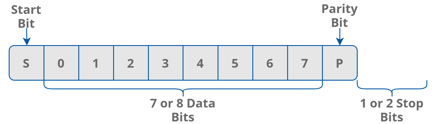
Modbus frame
Note: The BACnet protocol requires specific values of stop bits, data bits, and a parity bit of 1, 8, and none, respectively. Therefore, the user settings for these objects are not applicable.
REPLAY_DELAY: determines a number of milliseconds before the panel answers the request. This time is used to extend the interval between the request and response. The default value of 0 means no delay (the response is sent once during the 3,5 character required by the Modbus RTU protocol).
-
Modbus register 40021;
-
BACnet object: N/A.
WARNING!
The above parameters are remembered, but NOT automatically set. In order to set these parameters to the panel, it is required to perform one of the following actions after entering required values:
-
restart the panel;
-
send a reload settings command (0: 0x2FF, DEVICE (property: 3030): 0x2FF, iSMA Configurator, or FCU Updater).
Incoming data frames are counted and presented through the following parameters:
RECEIVED_FRAMES: shows the number of received frames. The register's value is reset at the start of the panel and at the change of transmission parameters;
-
Modbus register: 30004;
-
BACnet object: DEVICE, property: 5101;
ERROR_FRAMES: shows the number of error messages (shorter than 3 or with incorrect CRC value) received by the panel from the time of the last power-up. The register's value is reset at the start of the panel and at the change of transmission parameters;
-
Modbus register: 30006;
-
BACnet object: DEVICE, property: 5103;
TRANSMITTED_FRAMES: shows the number of sent frames. The register's value is reset at the start of the panel and at the change of transmission parameters;
-
Modbus register: 30008;
-
BACnet object: DEVICE, property: 5104.
USB
A USB bus is accessible through the USB C port at the bottom of the device. Device identifies itself as a USB HID, and can be configured using the iSMA Configurator and FCU Updater software.