
Touch Point Software User Manual
Introduction
The Touch Point is a modern comfort management wall panel with two most popular open communication protocols: Modbus RTU/ASCII and BACnet MS/TP. The Touch Point is available in different configurations of sensors (temperature, CO2, and humidity), colors, and versions with or without a display. The panel is equipped with a TFT display and touch buttons.
The panel can be configured using the iSMA Configurator software or Modbus registers/BACnet objects. It fits most of standard junction boxes in Europe and can easily be installed using a wall back box.
Revision History
Rev. | Date | Description |
|---|---|---|
1.0 | 20 Apr 2022 | First edition |
1.1 | 25 May 2022 | Editorial corrections |
Communication Protocols
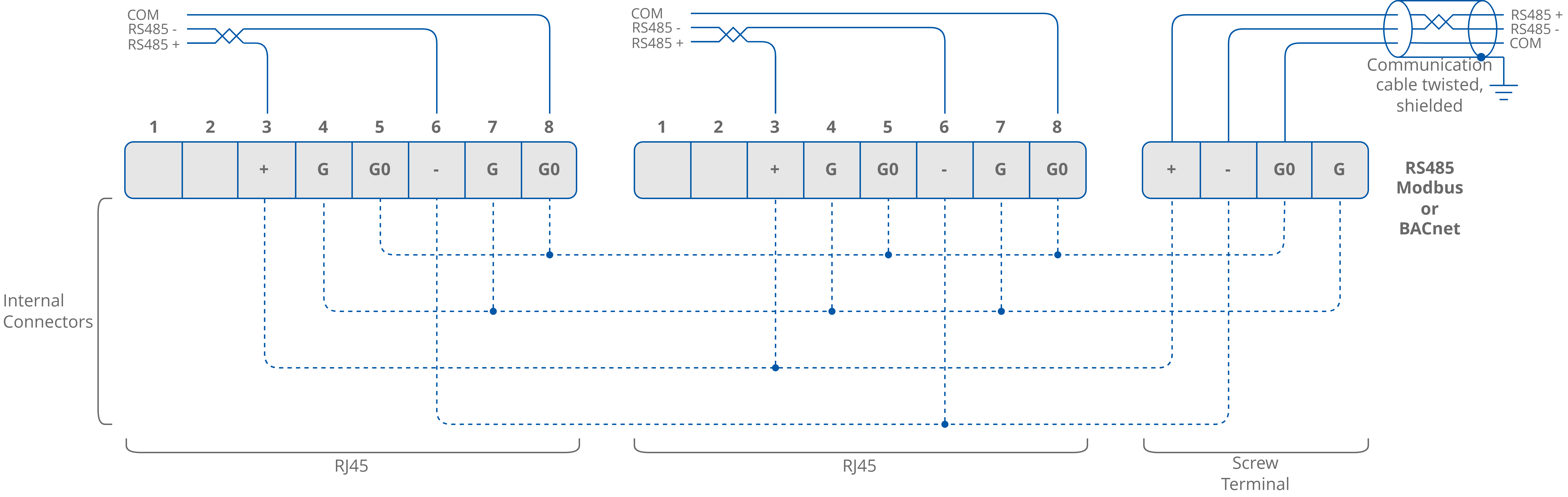
The Touch Point panel supports Modbus RTU/ASCII and BACnet MS/TP communication protocols, using 2 RJ45 sockets and a screw terminal (one RS485 port).
Note: A communication protocol is selected by setting a second switch on the DIP switch on the back of the panel:
Off: Modbus RTU/ASCII (default);
On: BACnet MS/TP.
The Modbus address of a server device is set using the rotary switch.
Note: If the rotary switch is set to 0, the address is read from the ADDRESS register/object (decimal address: 22). See Communication Parameters.
Other communication parameters such as baud rate, number of data/stop bits, or parity bit are set using relevant Modbus registers or BACnet objects.
RS485 Connection
RS485 Network Termination
Transmission line effects often present a problem for data communication networks. These problems include reflections and signal attenuation. To eliminate the presence of reflections of signal from the end of the cable, the cable must be terminated at both ends with a resistor across the line adequate to its characteristic impedance. Both ends must be terminated since the propagation is bidirectional. In case of an RS485 twisted pair cable this termination is typically 120 Ω.
Note: A termination resistor can be added with a third switch on the DIP switch on the back of the panel:
off: termination resistor disconnected (default);
on: termination resistor added.