Purpose and Description of the Module
The SfAR-S-6RO module is an innovative device that provides a simple and cost effective extension of the number of lines of output with high current-carrying capacity.
The module has 6 relay outputs. Each relay has three terminals: common (COM), normally open (NO), or normally closed (NC), which makes the unit very flexible.
This module is connected to the RS485 bus with a twisted-pair wire. Communication is via Modbus RTU or Modbus ASCII. The use of 32-bit ARM core processor provides fast processing and quick communication. The baud rate is configurable from 2400 to 115200.
The module is designed for mounting on a DIN rail in accordance with DIN EN 5002.
The module is equipped with a set of LEDs to indicate the status of inputs and outputs, power supply, and communication, which is useful for diagnostic purposes and helping to find errors.
Module configuration is done via USB by using a dedicated computer program. It also allows for changing the parameters using the Modbus protocol or setting the Modbus address using the DIP switches under the front panel.
Technical Specification
|
Power Supply
|
Voltage |
10-38 V DC; 10-28 V AC |
|---|---|---|
|
Power consumption (with active Modbus transmission and high state on all outputs) |
4.8 W at 24 V DC |
|
|
6 VA at 24 V AC |
||
|
Relay Outputs
|
No. of outputs |
6 |
|
Resistive load |
AC1: 8 A @ 230 V AC or 8 A @ 30 V DC |
|
|
Inductive load |
AC3: 360 V A @ 230 V AC or 60 W @ 30 V DC |
|
|
Isolation |
1000 V AC |
|
|
Temperature
|
Work |
-10 °C to +50°C (14°F to 122°F) |
|
Storage |
-40 °C to +85°C (-40°F to 185°F) |
|
|
Connectors
|
Power supply |
2 pins |
|
Communication |
3 pins |
|
|
Outputs |
2x 10 pins |
|
|
Quick connector |
IDC10 |
|
|
Configuration |
mini USB |
|
|
Size
|
Height |
119.1 mm (4.689 in) |
|
Length |
110.9 mm (4.366 in) |
|
|
Width |
22.7 mm (0.894 in) |
|
|
Interface |
RS485 |
Up to 128 devices |
Technical specification
Dimensions
The appearance and dimensions of the module are shown below. The module is mounted directly to the rail in the DIN industry standard. Power connectors, communication, and I/Os are at the bottom and top of the module. USB connector configuration and indicators are located on the front of the module.
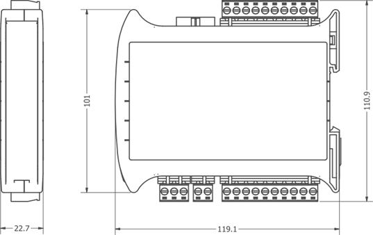
Dimensions