The RAC18-IP controller offers smart and easy way of creating applications.
The application created with the nano EDGE ENGINE device refers to containers:
-
Applications;
-
Networks;
-
Services.
The Applications container is where the main logic is contained; the Networks container is where the external communication is configured, and the Services container will be the place to connect with additional functionalities.
In order to create a fully functioning application follow these steps:
Step 1: Make sure that the device is correctly connected and set up. Detailed instructions are available in the device's (V1.1.0) RAC18-IP Quick Start-up (Step 1-7).
Step 2: Go to the Networks container to configure the external communication settings (Modbus or BACnet). Configure all the network-specific parameters there in order to enable proper communication in Modbus RTU as a client, Modbus TCP/IP as a server device, or in BACnet IP as a client or server device.
Step 3: Remain in the Network container. Go to the LocalIO component, and configure all input and output components that are going to be utilized in the main application logic. The input and output components are grouped in the IO library, available in the Device Libraries window. The first and foremost is to set their addresses (the Address slot in each input or output component)–unless the addresses are set properly, the components are in fault statuses.
Step 4: Go to the Applications container. This is the place to add Application components from the Core library–in fact, the nano EDGE ENGINE allows to add as many Application components to the container as necessary. Each application created this way is independent and cycle-driven. The (V1.1.0) Applications Manager is a view designed to manage Application components.
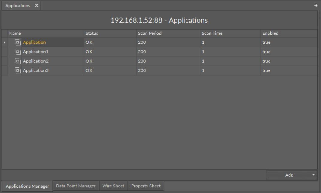
The Applications Manager
Good Practice Tip
In future developments, the RAC18-IP controller will have a Haystack functionality implemented in its firmware, which calls for some good practice mechanisms that can be introduced now, with the current functionalities.
The Haystack functionality will offer multiple advantages of using tags–it will help identify parts of equipment controlled by the application and used Data Points, filter data by equipment, sensor, or value, any many more.
In order to facilitate a future use of the full Haystack functionality, the Equipment component has been included in the Core library. It is therefore recommended to use the following structure when creating applications:
-
Applications container
-
Application component
-
Equipment component
-
Data Point(s)
-
other components
-
-
Equipment component
-
Data Point(s)
-
other components
-
-
-
Such structure will be fully recognized in the Haystack functionality and will require minimum effort to use its full potential once updated.
Difference Between Equipment and Folder Components
The Equipment component with Haystack functionality will allow to identify the types and other characteristics of controlled devices by tags, which will be a main difference between the Equipment and Folder components–the Folder component is merely an organizing component; in the future, it will not carry any Haystack tags functionalities. It is therefore very important to use the Equipment components in the applications structure.
Also refer to: Equipment Manager
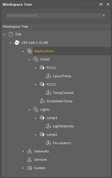
Step 5: (Recommended) Once all Application components are added to the Applications container, go to the Core library, and add Equipment components for each item controlled by the application. Then add Data Points to the Equipment components. It is advised to rename components to fit the application characteristics.
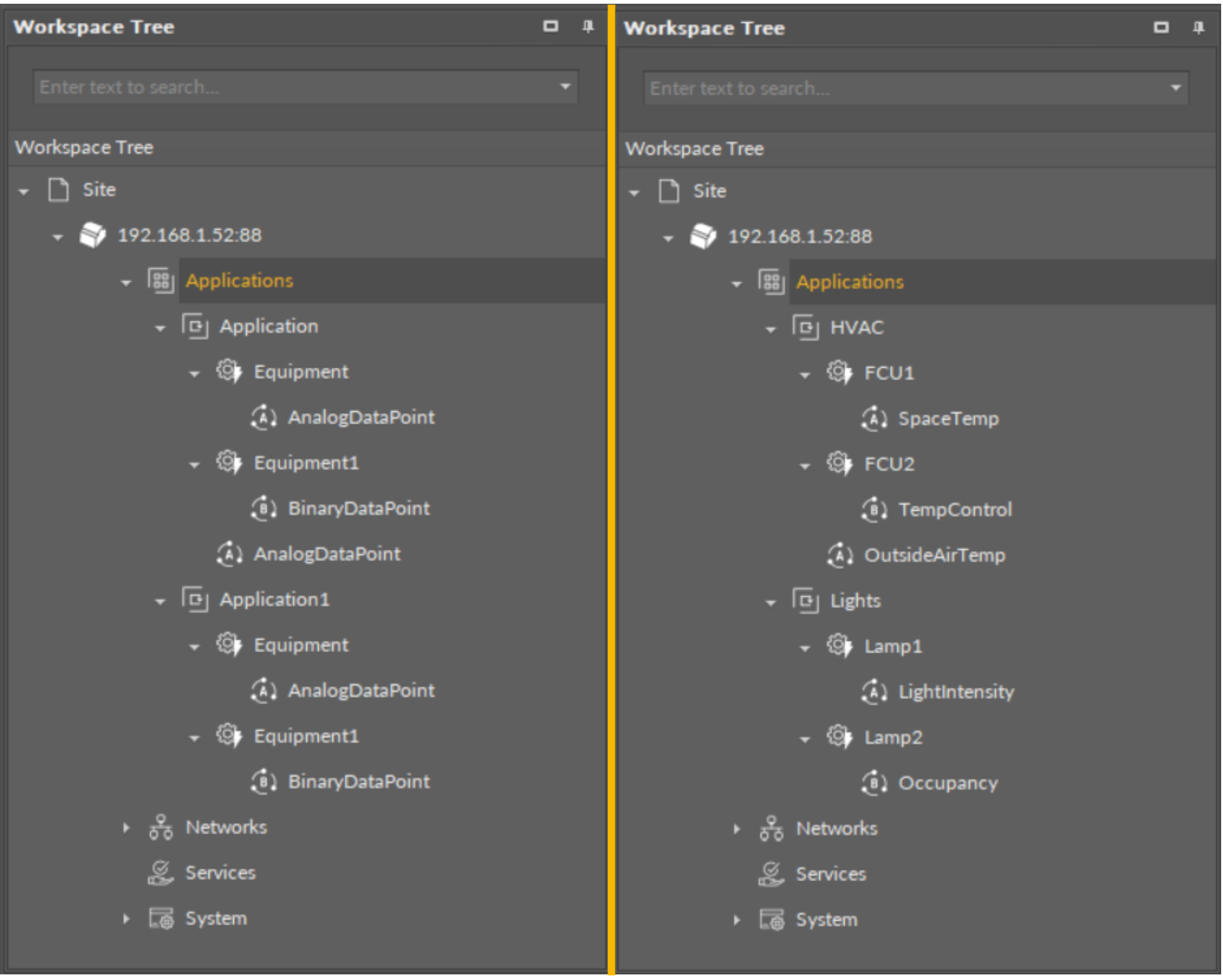
The recommended structure for applications
Step 6: (Recommended) Start adding other components to the Equipment component (or components) to create logics with added Data Points. All components available for creating applications are grouped in libraries in the Device Libraries window.
Tip
Data Points are universal components that represent a value in the application logic; they may serve as setpoints, sensors values, non-volatile variables, or any other data values. Data Points represent a layer of the application logic that is presented to an end user—this is where the end user is able to adjust desired setpoints (e.g., for air conditioning) or evoke other actions outlined in the application logic. Data Points also read values calculated in applications and control local or remote outputs.
Data Points in the application logic may work as regular writable variables with priorities, or—with Reference linking—they may be connected with network points, such as local IO components.
-
Analog Data Point;
-
Binary Data Point.
Step 7: Added component is ready to be linked. The nano EDGE ENGINE allows two methods of linking, standard and Reference linking. The Reference linking method is especially recommended to use to connect Data Points and network point class components. Detailed information is available in the (V1.1.0) Linking section. Detailed technical information about linking in the iC Tool is available in the Linking Components section.
Tip
Here is the list of other quick start-ups that offer detailed instructions on how to configure external communication, network points, explain linking methods, etc.: