Applicable to OS version 1.0.0.4592
The DigitalInputCounter component counts the pulses on rising edge in a physical digital input of the device. The counter may be employed, for example, to add up a number of pulses for used water meters or similar purposes. Before the DigitalInputCounter component is addressed to a physical input, the counter's default value is 0 and it changes once the slot starts reading values from a connected meter or sensor.
Note: If the component's Status is fault (e.g., an invalid value in the Address slot), the counter's value is null.
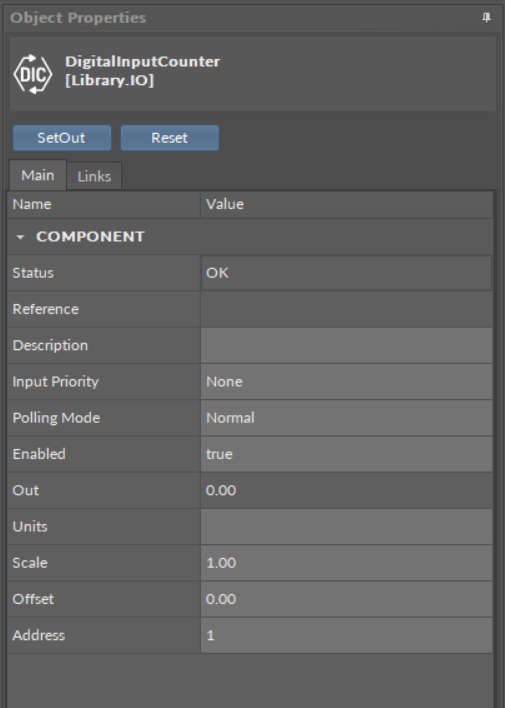
The DigitalInputCounter component
Slots
The DigitaIInputCounter component has the following slots:
-
Status: indicates the current status of the component; if the component works properly, its status is OK. The component becomes Disabled, once the Enabled slot is in false. The component's status is Fault, once the Address slot is null, 0, or exceeding an available range;
-
Available information: Disabled, Fault, OK;
-
-
Reference: a special slot allowing to connect network point class components with Data Point class components. It allows to transfer the Out slot value along with the component's status.
By default, once the Reference link is created from the network point to the Data Point it sets the input priority to 16, which later can be changed manually.
-
Description: an additional detailed information about a service that may be freely described by the user; the description may contain individual coding, defined in the user's system documentation, or any other information the user finds applicable.
-
InputPriority: allows to select the input number in the Data Point, which the value from the network point class component's output is sent to; by default, the priority is None and sets to 16 after linking with a Data Point (can be changed manually).
-
Available settings: none, 1-16.
-
Note: The Reference link from the network point to the Data Point cannot be changed to a 17th, default, priority.
-
Polling Mode: allows to set the frequency of sending polling requests for the point's value—by default, the polling mode is set to normal;
-
Available settings: fast, normal, slow;
-
-
Enabled: change of the slot's value enables or disables the component—if the component becomes disabled, it stops to read values from the physical input; by default, the component is enabled.
-
Available settings: true (enabled), false (disabled).
-
Note: If the Enabled slot is in false (meaning the component is disabled), the Status slot becomes Disabled.
-
Out: shows a number of rising edges from the physical digital input of the address set in the Address slot.
Note: If the component's Status is fault (e.g., an invalid value in the Address slot), the Out value is null.
-
Units: defines a unit of the Out slot value; no unit is set by default;
-
Scale:
sets a fixed scaling factor for output linearization; the Out value is calculated according to the linear function formula (y=ax+b), and the Scale slot set the a value of the formula;
-
Offset: sets a fixed offset value to the output value; the Out value is calculated according to the linear function formula (y=ax+b), and the Offset slot set the b value of the formula;
-
Address: allows setting an address of a physical input of the device; once the component has been added, the slot's default value is null—for the component to operate properly, the unique address value must be set in this slot.
-
Available settings: 1-n, where "n" stands for the number of actual inputs in the device.
-
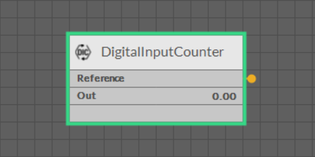
The DigitalInputCounter component linked
Actions
-
SetOut: sets the Out slot to a specific value;
-
Reset: sets the Out slot to the 0 value.