Step 1: Network configuration
(a) The DALI component, which is by default added in the Networks container, is responsible for enabling the DALI-2 protocol communication in the controller. Make sure that the component is enabled for further configuration.
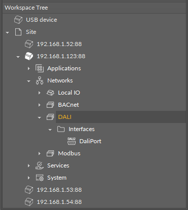
(b): Expand the Interfaces folder. Make sure that the selected DALI port is enabled.
(c): To proceed with network configuration, it is required to add components starting from the Network component from the Core library. The Network component has to be located under the DALI component. Make sure that the component is enabled and configured.
Note
To facilitate managing networks, the Network Manager view is available in the DALI’s component context menu or by double-click on the DALI component.
Step 2: DALI power mode
Next, define the DALI bus power supply. Go to the Network component and set the Dali Power Mode slot to enabled or disabled state.
The DALI power mode slot set to enabled means that the internal power supply is activated—the DALI-2 bus is powered directly from the controller’s DALI port.
🔌 The internal power output guarantees 12 V at up to 125 mA current, with 170 mA maximum current.
The DALI power mode slot set to disables means that the DALI-2 bus is powered externally.
🔌 The maximum current load on the DALI-2 bus with external power supply is 250 mA, which also applies to combined internal and external power supply.
Step 3: Discovering
(a) Follow by discovering devices on the network (ControlGear, DT8_CCT, DT8_RGBW, InputDevice).
Discovering devices on the network is automated in dedicated DALI views: in iC Tool (DALI Device Discover and Device Manager) or nE2 Link module.
Discovering modes
-
Discover Initialized Devices: discovers all devices which have a short address assigned,
-
Full Reinitialization: discovers all devices on the bus, clears assigned short addresses, and assigns new short addresses to discovered devices,
-
Initialize Unassigned Devices: discovers devices on the bus with an unassigned short address and assigns a first free short address to the(se) device(s).
Supported devices
The DALI-2 implementation in the nano EDGE ENGINE supports the following devices:
-
control gear devices:
-
DT0: fluorescent lamps,
-
DT1: emergency lighting,
-
DT2: discharge (HID) lamps,
-
DT3: low-voltage halogen lamps,
-
DT4: incandescent lamps,
-
DT5: conversion to DC voltage (1-10 V, 0-10 V converter),
-
DT6: LED modules,
-
DT7: switching (relay) devices,
-
DT8: color control (e.g., tunable white, RGBW);
-
Note: The nano EDGE ENGINE implementation supports control gear devices according to the IEC-62386-102 standard and DT8 devices with functionalities according to the IEC-62386-209 standard.
-
input devices:
-
generic inputs,
-
absolute inputs,
-
push buttons,
-
light sensors,
-
occupancy sensors.
-
(b) The next step is to discover control gear’s points and input devices' instances.
Discovering points and instances to devices is automated in dedicated DALI views: in iC Tool, DALI Point Manager (for control gear’s points) and DALI Instance Discover (for input devices' instances), or in nE2 Link module.
Make sure that the short addresses are properly correlated between device-class components and points/instances—it is crucial for establishing communication between devices. To facilitate short addresses verification, the Identify action is available in the DALI Device Discover view; it makes the selected device blink allowing an easy identification of a physical device with its assigned short address.
Step 4: Groups and scenes management
Proceed to DALI groups and scenes management. To this end, a dedicated view is available, DALI Groups and Scenes. The groups and scenes manager allows to adjust settings for:
-
16 DALI groups,
-
16 DALI scenes,
-
16 DT8_CCT scenes,
-
16 DT8_RGBW scenes.
Step 5: Commands
Lastly, use command-type components (SendCommand, EncodedSendCommand, CCTSendCommand, RGBWSendCommand) to connect physical DALI-2 devices to the controller’s application. The Command Manager view is available for a facilitated adding of commands.