Applicable to OS V1.10
The Network component allows to configure the BACnet (IP or MS/TP) or Modbus (TCP/IP or RTU) client network and the DALI-2 network. It allows to add remote devices (using the Device-class components) and configure basic polling schedule for such devices and their points.
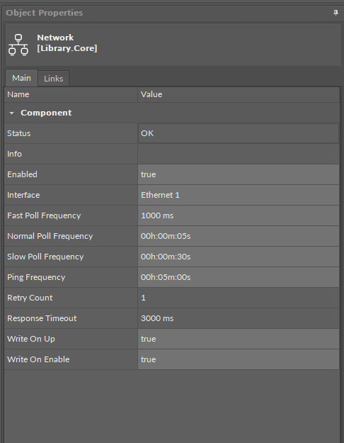
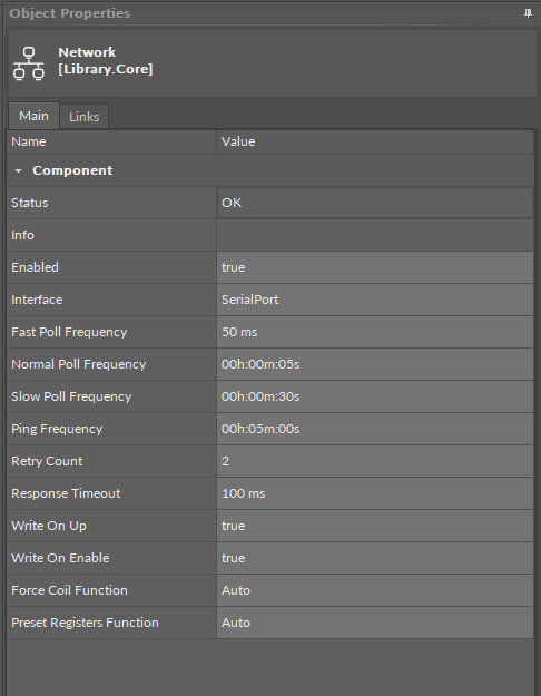
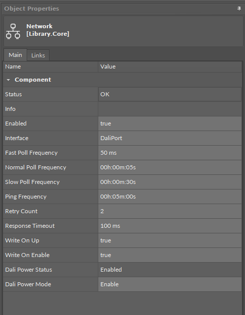
The Network component has the following slots:
-
Status: indicates the current status of the component. If the component works, its status is OK; the component's status becomes Disabled if its Enabled slot has been set to false.
-
Available information: Disabled, OK.
-
-
Info: provides a detailed information about the Disabled and Fault statuses of the component;
-
Available information:
-
Could not find selected Port (status Fault): occurs, for example, when the interface set for the network gets deleted;
-
Incorrect placement - must be placed under a network protocol (status Fault): occurs, when the Network component is placed in a different location than under the BACnet/Modbus/DALI component in the Networks container;
-
Could not find Interfaces container (status Fault): occurs if the Interfaces folder gets manually removed;
-
Network disabled (status Disabled): the Enabled slot in the Network component is set to false;
-
Interface disabled (status Disabled): the Enabled slot in the interface component (IpPort/SerialPort/DaliPort), assigned to the network, is set to false;
-
-
The Info is a numerical slot, which displays a correlated text information:
|
Numerical value |
Displayed information |
|---|---|
|
0 |
No information displayed in the Info slot |
|
1 |
Could not find selected Port |
|
2 |
Incorrect placement - must be placed under a network protocol |
|
3 |
Could not find Interfaces container |
|
4 |
Network disabled |
|
5 |
Interface disabled |
-
Enabled: change of the slot's value enables or disables the component;
-
Available settings: true (enabled), false (disabled);
-
Note: If the Enabled slot is in false (meaning the component is disabled), the Status slot becomes Disabled.
Note
In order for the network to be enabled, the Ethernet component (for BACnet IP, Modbus TCP/IP), the Serial component (for BACnet MS/TP, Modbus RTU), and the Dali Port configured for the port defined in the Adapter slot (or Serial Port slot for the DALI network), has to be enabled too.
-
Interface: allows to set the Ethernet interface for BACnet IP or Modbus TCP/IP client network, the Serial port for BACnet MS/TP or Modbus RTU, and the Dali port for the DALI-2 network;
-
Fast Poll Frequency: sets the time between requests for the point’s value sent in the fast mode;
-
Normal Poll Frequency: sets the time between requests for the point’s value sent in the normal mode;
-
Slow Poll Frequency: sets the time between requests for the point’s value sent in the slow mode;
Note
To avoid overloading of the Modbus communication, writing values occurs in the following cases:
-
change of value by link,
-
the Action Trigger extension is executed,
-
the Set action is executed.
-
Ping Frequency: sets the time between testing requests to check the device’s connection;
-
Retry Count: shows a number of repeated requests;
-
Response Timeout: time set to wait for the device's response;
-
Write On Up: allows to send all network points values to points in server devices on the network when the devices go from the Down status to OK;
-
Write On Enable: allows to send all network points values to points in server devices on the network when the devices go from Disabled to Enabled.
Note
The Write On Up and Write on Enable functions are applicable to the following points on BACnet and Modbus networks:
-
BACnet:
-
AnalogPoint,
-
BinaryPoint,
-
MultistatePoint;
-
-
Modbus:
-
AnalogPoint,
-
BinaryPoint,
-
MultistatePoint,
-
StringPoint.
-
For DALI-2 protocol, are applicable to the following points:
-
ControlGear points (AnalogActualLevel, BinaryActuallevel): additionally to values, the Write On Up and Write on Enable functions send also the components’s parameters (Min Level, Max Level, Power On Level, System Failure Level, Fade Time, Fade Rate, Group, Scene0-15 Level);
-
InputDevices points (GenericInput, AbsoluteInput, PushButton, LightSensor, OccupancySensor): additionally to value, the Write On Up and Write on Enable functions send also the components’s parameters (Event Messages Enabled, Event Scheme, Event Priority, Primary Instance Group).
Slots applicable only for the Modbus network:
-
Force Coil Function: allows to specify whether to force Modbus function 15 for all coil write operations on the device or use network settings;
-
Preset Register Function: allows to specify whether to force Modbus function 16 for all register write operations on the device or use network settings.
Slots applicable only for the DALI-2 network:
-
Dali Power Status: informs about the status of an internal power supply for the DALI-2 bus;
-
Dali Power Mode: allows to enable/disable a controller’s internal power supply for the DALI-2 bus.
Note
-
The DALI power mode slot set to enabled means that the internal power supply is activated—the DALI-2 bus is powered directly from the controller’s DALI port.
The internal power output guarantees 12 V at up to 125 mA current, with 170 mA maximum current.
-
The DALI power mode slot set to disables means that the DALI-2 bus is powered externally.
The maximum current load on the DALI-2 bus with external power supply is 250 mA, which also applies to combined internal and external power supply.