The Modbus library includes components that control the Modbus RTU client and Modbus TCP/IP client and server communication implemented in the device. It allows the device to
-
be recognized and identified in the Modbus TCP/IP network as a Modbus server device, and to
-
work as a Modbus RTU or TCP/IP client device (sending requests to Modbus server devices for their registers values).
In the nano EDGE ENGINE V1.2, in the LocalDevice (RAC18-IP) component, there is an extension informing about a device exposition to the Modbus RTU network as a server device through a serial port, however, please note that this functionality is prepared strictly for a future use.
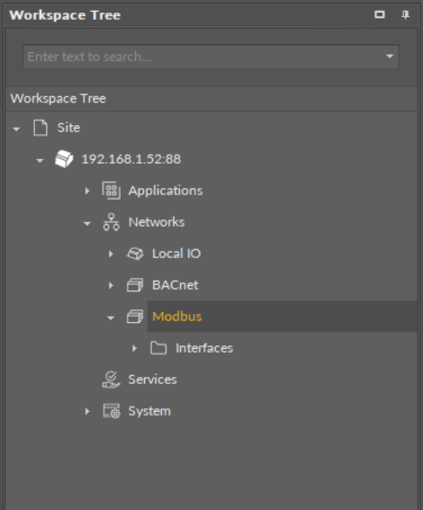
The Modbus RTU communication is handled via the RS485 port, while Modbus TCP/IP commmunication is handled via IP. In order to operate properly, the Modbus library components have to be placed in the Networks container (the Modbus component being the superior, service-type component).
The Modbus library
Modbus Component
The essential feature of the Modbus management in the nano EDGE ENGINE devices is the Autoexposition option–allowing all Data Points added in the project to be exposed to the Modbus TCP/IP network by default. If the Autoexposition slot in the Modbus component is set to true, all Data Points added in the project are automatically exposed on the Modbus TCP/IP network as Modbus points; however, Data Points may then be individually hidden from the network by manually changing the Expose slot value in a Data Point's Modbus extension (i.e., native extensions, ModbusAnalogPoint and ModbusBinaryPoint, in Analog and Binary Data Points). In case the Autoexposition slot is set to false, all new added Data Points are automatically hidden from the network. They may be exposed to the network manually, changing the Expose slot value in Data Point's Modbus extensions to true.
The Modbus component can be either enabled, or disabled, using the Enabled that manually starts or stops the whole Modbus component. Stopping it makes the device and its Modbus points invisible in the Modbus TCP/IP network.
The Modbus component is automatically added and cannot be removed from the device.
The Modbus component
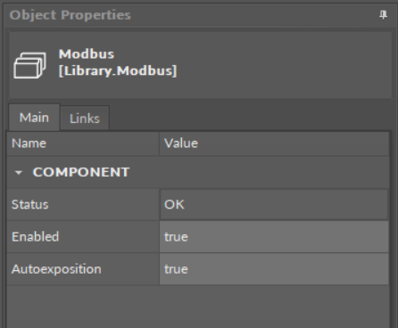
The Modbus component has the following slots:
-
Status: indicates the current status of the component. If the component works properly, its status is OK; if the Enabled slot has been set to false, the components's status becomes Disabled. The component goes into the Fault status if it cannot be started.
-
Available information: Disabled, Fault, OK.
-
-
Enabled: change of the slot's value enables or disables the component.
-
Available settings: true (enabled), false (disabled).
-
Note: If the Enabled slot is in false (meaning the component is disabled), the Status slot becomes Disabled.
-
Autoexposition: allows to automatically define the exposition of all Data Points added in the project to the Modbus TCP/IP network.
-
Available settings: true (exposed), false (hidden).
-
The Modbus component slots
Modbus RTU or TCP/IP Client Network
In order to configure the Modbus RTU or TCP/IP client network, follow these steps:
Step 1:
(a) Double-click the Modbus component–the Device Libraries now displays the Core library and the Network component in it. Drag and drop the Network component to the Modbus component; or
(b) Double-click the Modbus component–the Wire Sheet now displays the Network Manager. Add the Network component using the Add button in the bottom right corner of the sheet.
Step 2: Set the Network's component Enabled slot to true. Configure the rest of the slots if necessary.
Step 3:
(a) Double-click the added Network component–the Device Libraries now displays the Modbus library and the Device component in it. Drag and drop the Device component to the Network component. In the pop-up window, it is possible to set the quantity of components to add. Add as many Device components as there are responding devices in the network; or
(b) Double-click the added Network component–the Wire Sheet now displays the Device Manager. Add the Device component using the Add button in the bottom right corner of the sheet.
Step 4: In each added Device component, set its Enabled slot to true. Set the Address slot and the rest of the slots (if necessary).
Step 5:
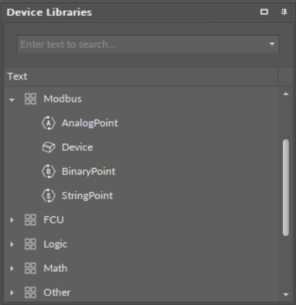
(a) Double-click the Device component–the Device Libraries window now displays the Modbus library and the AnalogPoint/BinaryPoint/StringPoint components. Drag and drop as many points as required; or
(b) Double-click the Device component–the Wire Sheet now displays the Point Manager. Add points using the Add button in the bottom right corner of the sheet.
Step 6: Configure each added AnalogPoint/BinaryPoint/StringPoint component.
Modbus TCP/IP Server Network
Thanks to the Autoexposition function, all Data Points in the device are automatically exposed as the Modbus server device. In order to disable the Data Point in the Modbus server network, either set the Autoexposition slot in the Modbus component to false (all Data Points hidden), or go to each Data Point individually and set the Expose slot to false.