The DALI-2 protocol enables an advanced lighting control. In the nano EDGE ENGINE implementation, there is a dedicated DALI library, which allows for the DALI-2 port and network configuration, management of DALI-2 control gear and input devices with instances, and commands management.
The DALI-2 protocol in the nano EDGE ENGINE implementation is designed for application controllers that natively support the DALI protocol and are equipped with the DALI port (for example, the ZAC24-IP controller).
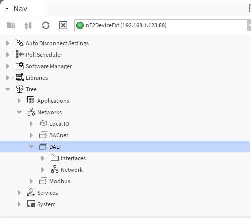
Configuration of the DALI-2 network on such controllers is straightforward. With the nano EDGE ENGINE OS V1.10, once the DALI library is installed on the controller, the DALI component is automatically added in the Networks container with the Interfaces and Network component.
DALI
The DALI component is responsible for enabling the DALI-2 protocol communication in the controller.
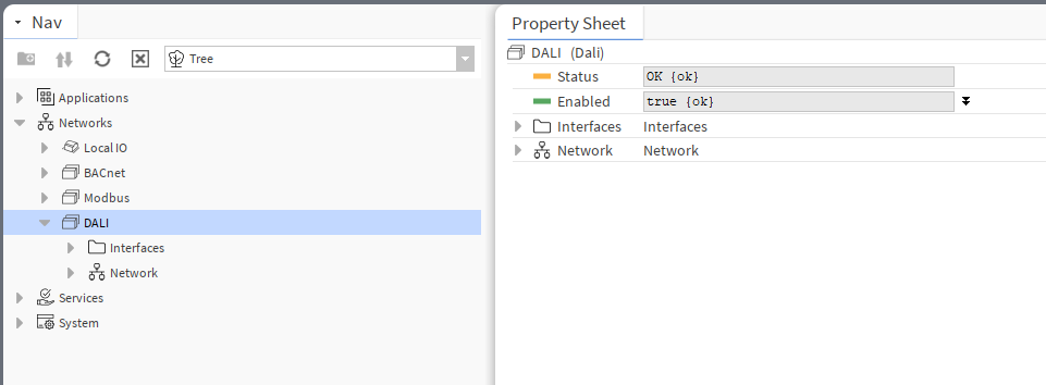
Make sure that the component is enabled for further configuration.
Interfaces
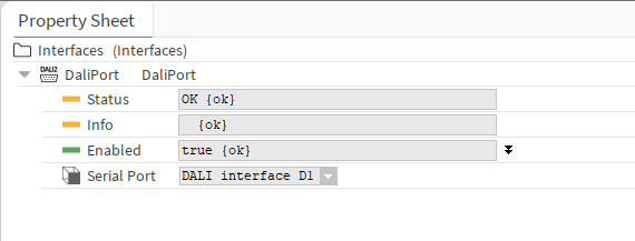
The Interfaces folder contains DALI ports available in the controller. If more than one port is available, it is possible to select a port for DALI-2 communication. The port can be enabled/disabled in the component’s Enabled slot.
The DALI and Interfaces components are added by default in controllers natively supporting the DALI-2 protocol. To proceed with network configuration, it is required to add components starting from the Network component from the Core library, followed by components from the DALI library.
Network
The Network component has to be located under the DALI component.
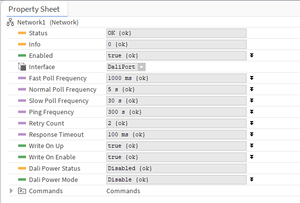
In the Network component, it is possible to configure typical network parameters (enabling, polling frequency, retry counts, timeout) and parameters specific to the DALI network.
In the DALI configuration, the WriteOnUp and WriteOnEnable functions send not only values, but also DALI-specific parameters:
-
ControlGear points (AnalogActualLevel, BinaryActuallevel): additionally to values, the Write On Up and Write on Enable functions send also the components’s parameters (Min Level, Max Level, Power On Level, System Failure Level, Fade Time, Fade Rate, Group, Scene0-15 Level);
-
InputDevices points (GenericInput, AbsoluteInput, PushButton, LightSensor, OccupancySensor): additionally to value, the Write On Up and Write on Enable functions send also the components’s parameters (Event Messages Enabled, Event Scheme, Event Priority, Primary Instance Group).
The Dali Power Mode function allows to enable/disable a controller’s internal power supply for the DALI-2 bus.
Note: It is important to avoid double power supply on the bus and internally from the controller to prevent a short circuit.
Along with the Network component, the Commands folder is added automatically. The folder is designed for command-type components from the DALI library: SendCommand, EncodedSendCommand, CCTSendCommand, and RGBWSendCommand.
Default Views
The next step of the DALI-2 network configuration is to add devices and their points.
The DALI-2 implementation in the nano EDGE ENGINE supports the following devices:
-
control gear devices:
-
DT0: fluorescent lamps,
-
DT1: emergency lighting,
-
DT2: discharge (HID) lamps,
-
DT3: low-voltage halogen lamps,
-
DT4: incandescent lamps,
-
DT5: conversion to DC voltage (1-10 V, 0-10 V converter),
-
DT6: LED modules,
-
DT7: switching (relay) devices,
-
DT8: color control (e.g., tunable white, RGBW);
-
-
input devices:
-
generic inputs,
-
absolute inputs,
-
push buttons,
-
light sensors,
-
occupancy sensors.
-
Adding devices to the network is automated in dedicated DALI views.
Dali Device Manager
The Dali Device Manager allows to automatically discover devices available in the DALI-2 network.
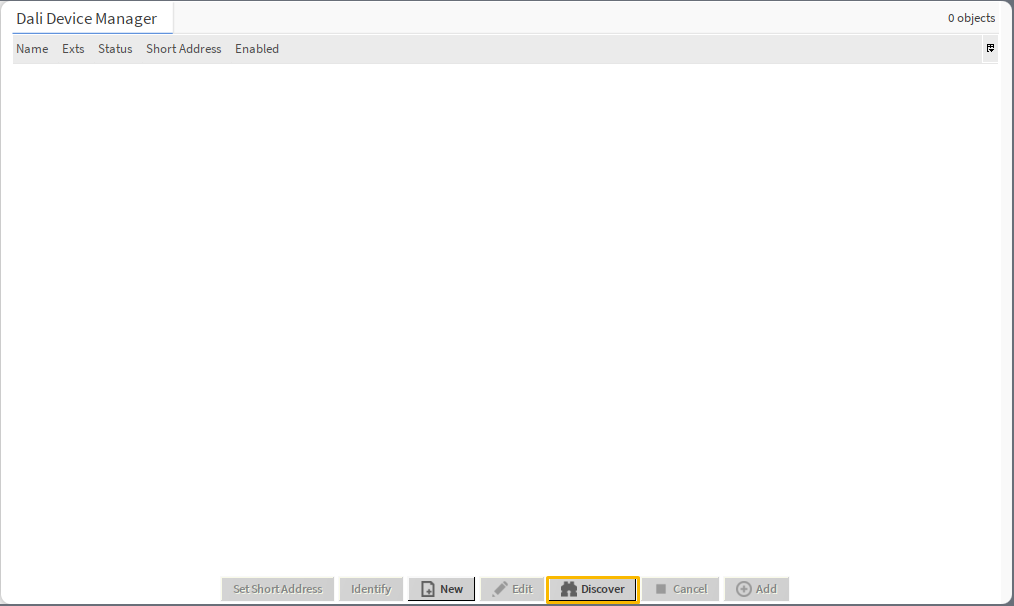
The Dali Device Manager is available on double-click on the Network component or in the component’s context menu.
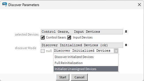
To initiate the discovery process, press the Discover button. A dialog window pops up where it is possible to set the discover parameters:
-
Selected Devices: allows to select a type of devices to discover,
-
Available settings: control gear, input devices;
-
-
Discover Mode: allows to select a mode of discovering:
-
Available settings:
-
Discover Initialized Devices: discovers all devices which have a short address assigned,
-
Full Reinitialization: discovers all devices on the bus, clears assigned short addresses, and assigns new short addresses to discovered devices,
-
Initialize Unassigned Devices: discovers all devices on the bus and assigns short addresses to devices which have been unassigned.
-
-
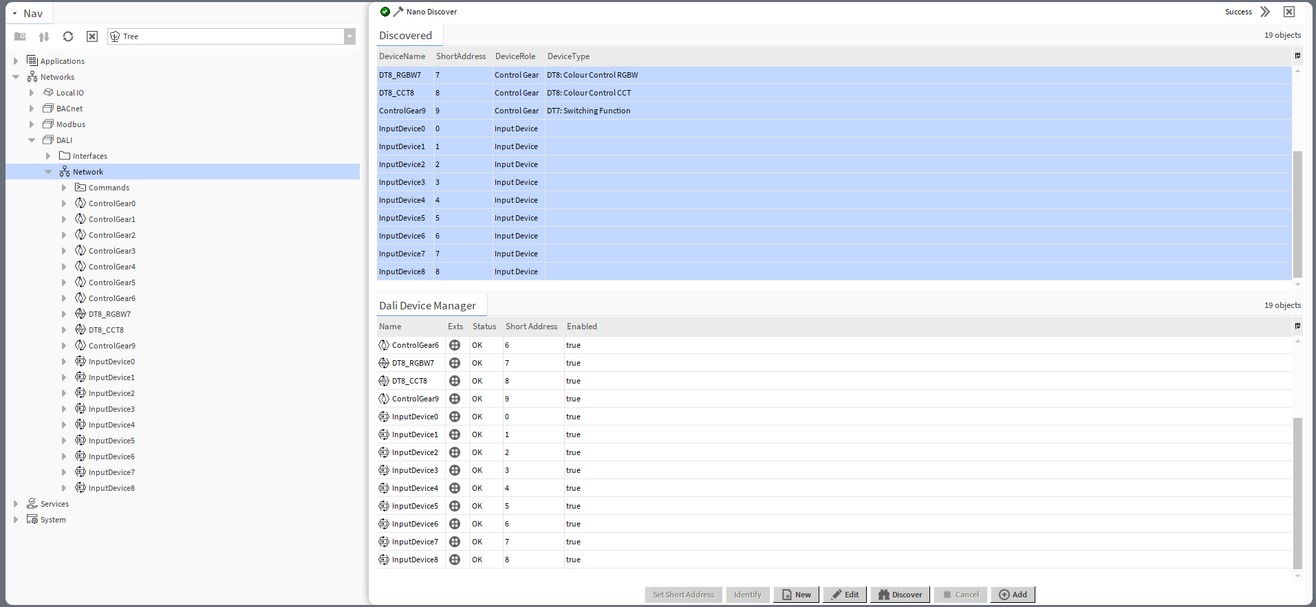
In the discovery process, the window is split in two: the top window (Discovered) with discovered devices and bottom window (Dali Device Manager), a location to add discovered devices. When the devices are added to the Dali Device Manager window, they are automatically added to the device tree under the Network component.
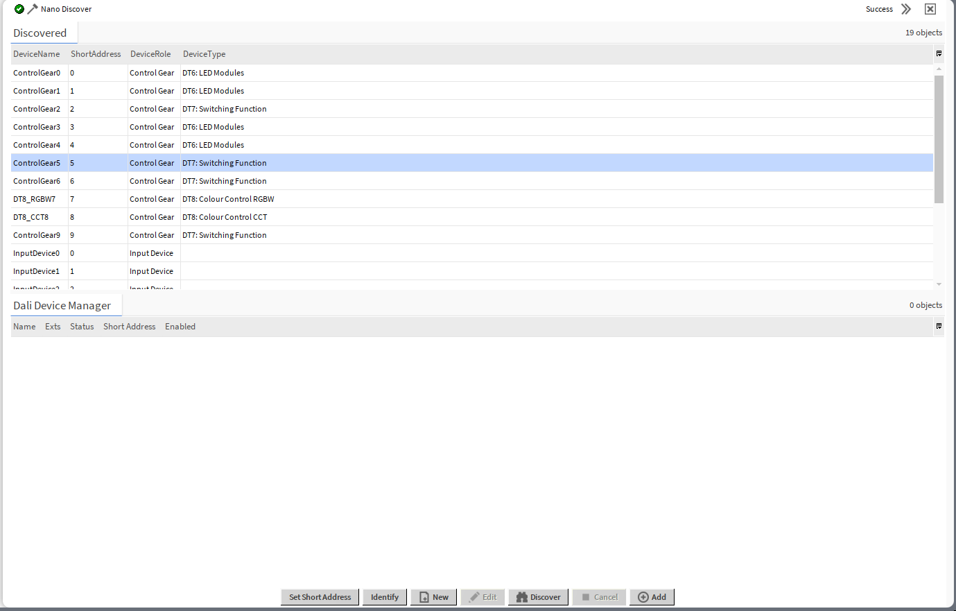
The Discovered window displays the following information about the devices:
-
DeviceName: shows a discovered device’s name;
-
ShortAddress: shows a device’s assigned DALI short address;
-
DeviceRole: shows a DALI-2 device type, control gear or input device;
-
DeviceType: (applicable for control gear) identifies a DALI-2 type of discovered control gear (DT0-DT8).
For discovered devices, the Dali Device Manager view has the following actions:
-
Set Short Address: allows to set a new short address to the discovered device,
Note
The Set Short Address action in the DALI Device Manager view is the only way to assign a short address to a remote device. Device-class components (ControlGear, InputDevice) have the Short Address slots, however, values entered in these slots are applied only locally, in the controller’s logic, they are not sent to the remote device. If short addresses in the remote device and corresponding component are different, the communication is broken and the component goes into the Down status. The only way to effectively change the short address in the remote device is to set it from the DALI Device Manager view.
-
Identify: sends the Identify DALI command to a remote device for identification,
Note
Once the Identify DALI command is successfully sent to the device, it returns a clear identification signal, e.g., blinking.
-
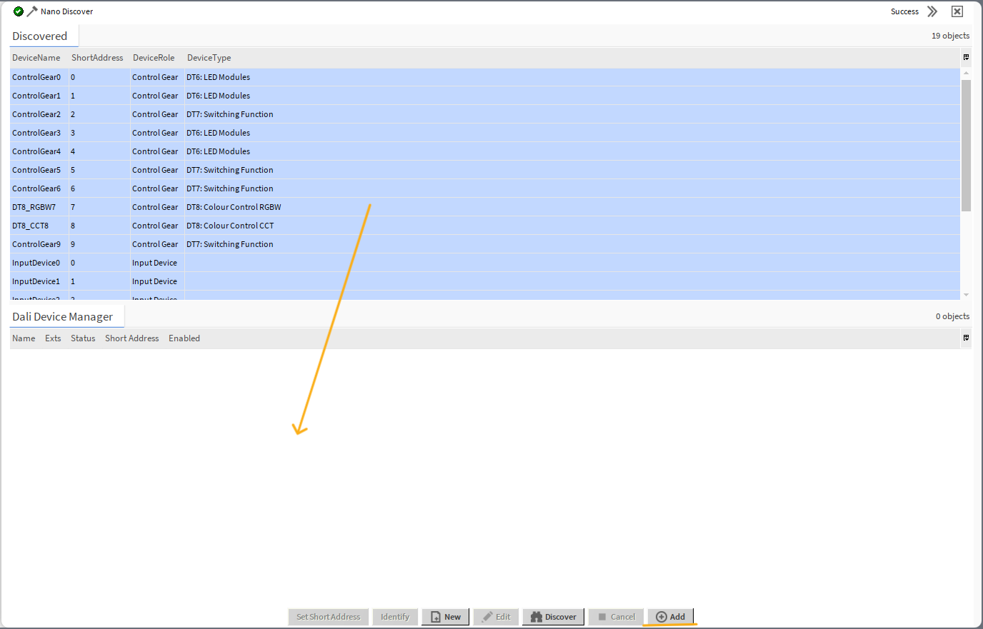
Add: adds the device to the DALI-2 network in the Workspace Tree.
To add discovered devices drag and drop them or use the Add button - if the list includes a lot of devices to add, first, use the Select All option from the context menu).
In the Dali Device Manager view, it is also possible to add the device manually. To this end, use the New button, which opens a dialog window:
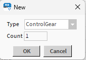
In the dialog window, it is possible to select a type of the component to add (ControlGear, InputDevice, DT8_CCT, DT8_RGBW, DeviceFolder) and a number of components to add. Added components are automatically visible in the Dali Device Manager view and in the nav tree.
To add the input devices’s instances, proceed to the Dali Instance Manager view.
To add points to the control gear components, proceed to the Point Manager available on a double-click on a component.
Dali Instance Manager
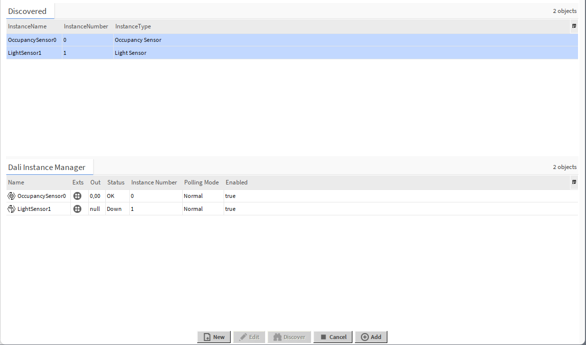
The Dali Instance Manager view allows to automatically discover instances of DALI-2 input devices added to the DALI network.
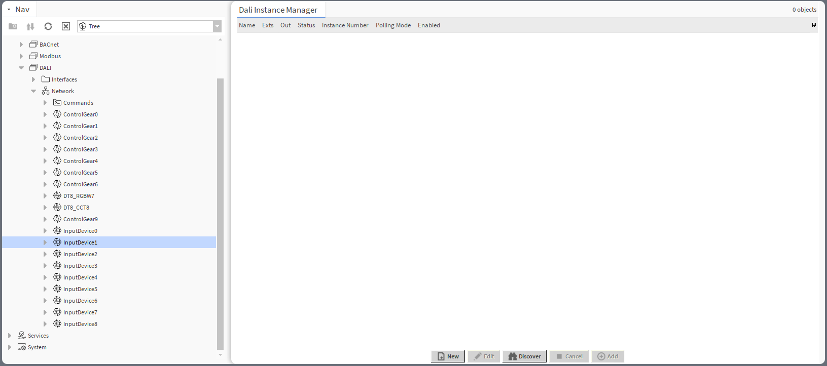
The Dali Instance Manager is available on double-click on the InputDevice component or in the component’s context menu.
To initiate the discovery process, press the Discover button.
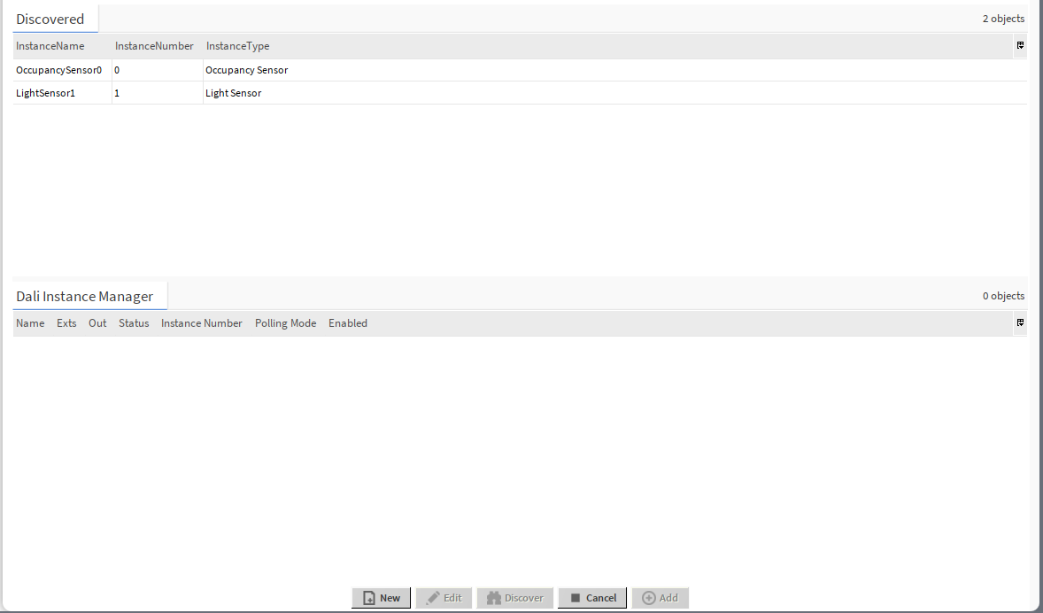
All instances discovered for the input device are listed with the following information in three columns:
-
InstanceName: shows a discovered instance's name;
-
InstanceNumber: shows an instance address of the point in the DALI-2 input device;
-
InstanceType: shows a type of the discovered instance.
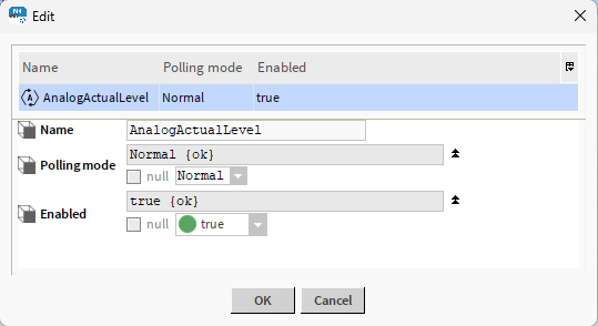
For a selected instance, the Dali Instance Manager has an editing action:
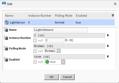
In the editing dialog window, it is possible to change the instance number, polling mode, and enable/disable the point.
Discovered points can be easily added to the InputDevice component. Select the points on the list and click the Add button.
In the Dali Instance Manager view, it is also possible to add the point manually. To this end, use the New button, which opens a dialog window:
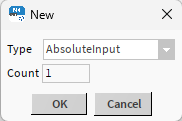
In the dialog window, it is possible to select a type of the component to add (AbsoluteInput, GenericInput, PushButton, LightSensor, OccupancySensor, PointFolder) and a number of components to add. Added components are automatically visible in the Dali Instance Manager view and in the nav tree.
Dali Point Manager
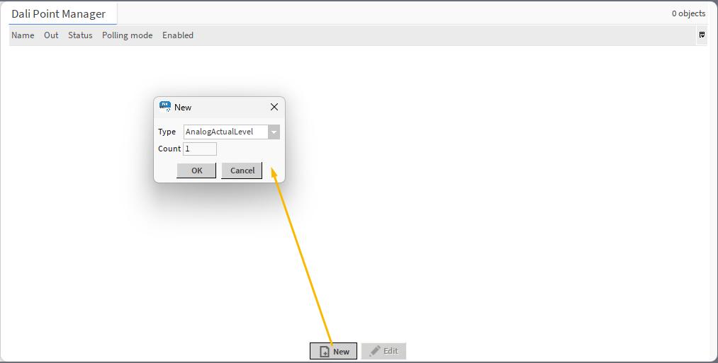
The Dali Point Manager view allows to manually add and manage points for the control gear.
The Dali Point Manager is available by a double-click on a control gear or in the component’s context menu.
To add a new point, use the Add button. A dialog window pops up where it is possible to select the type of the point (AnalogActualLevel, BinaryActualLevel, CGStatus) or PointFolder, and the number of components to add. Added components are automatically visible in the manager and in the nav tree.
The the Dali Point Manager, it is also possible to edit points. To this end, select the point and use the Edit button.
In the editing window, it is possible to change the name of the component, its polling mode, and enable/disable the component.
Dali Groups Manager
The Dali Groups Manager shows all ControlGear devices added to the DALI network and allows to assign them to a specific group (or groups), which can represent a location, type of device, role, etc. Groups allow for a collective management of assigned devices by sending commands to grouped devices.
All listed devices can be assigned to any of the 16 groups.
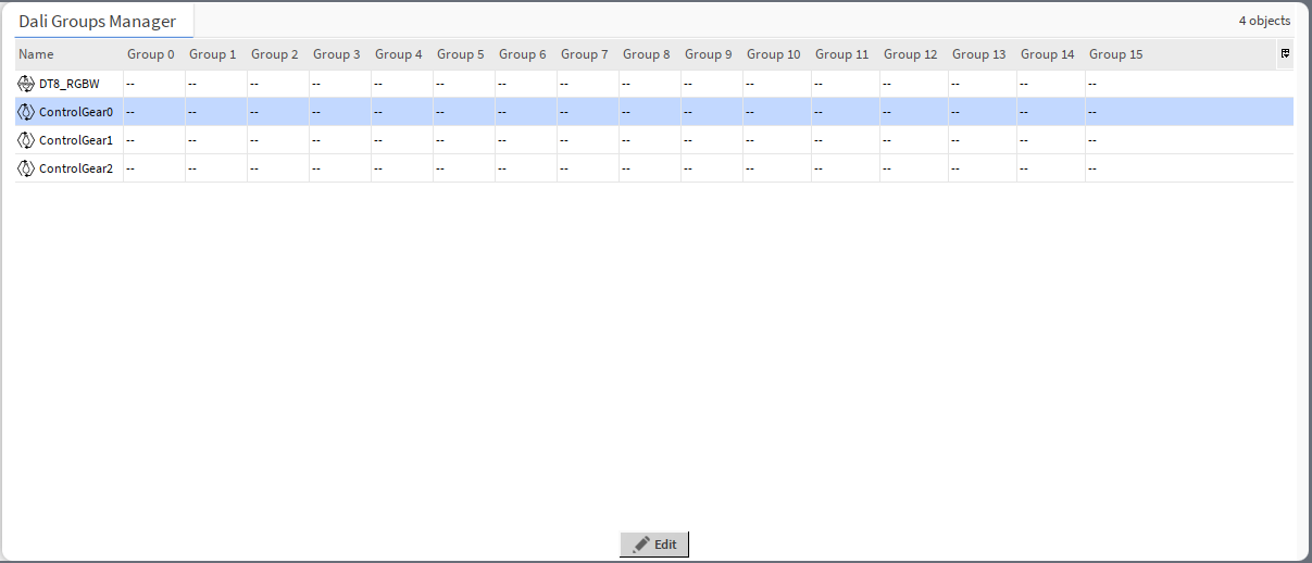
Groups are assigned by a double-click on a control gear’s row. The editing dialog window pops up, where it is possible to assign the device to multiple groups:
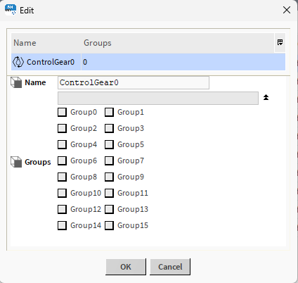
Use the check boxes to assign the device to a group. Confirm changes with OK. The changes will automatically be applied in the Dali Groups Manager view.
Dali Scenes Manager
The Dali Scenes Manager allows to set the light intensity to control gear devices.
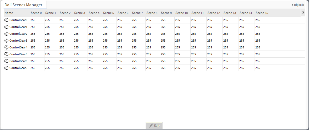
Note: Values 0-254 represent actual lighting levels and a 255 value means that when a specific scene is recalled, a device should not change its lighting level (MASK value).
Scene values are editable by a double-click on a control gear’s row. The editing dialog window pops up, where it is possible to assign the scenes' values:
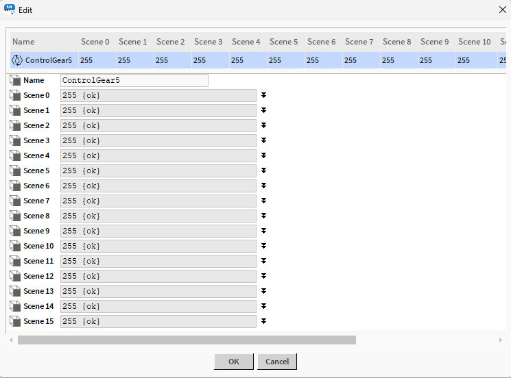
Edit values for each scene separately. Confirm changes with OK. The changes will automatically be applied in the Dali Scenes Manager view.
Dali Scenes CCT Manager
The Dali Scenes CCT Manager allows to set the light intensity and color temperature for DALI DT8 (Color Control) devices.
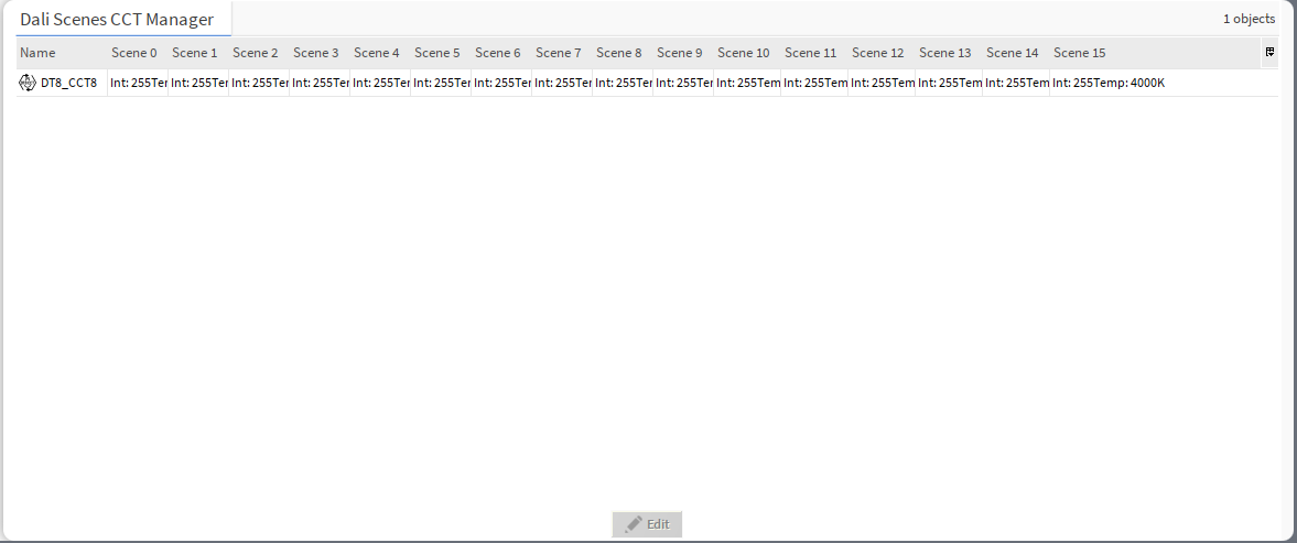
Note: Values 0-254 represent actual lighting levels and a 255 value means that when a specific scene is recalled, a device should not change its lighting level (MASK value).
Each scene value is editable by a double-click on control gear’s row. The editing dialog window pops up, where it is possible to assign the scenes' values:
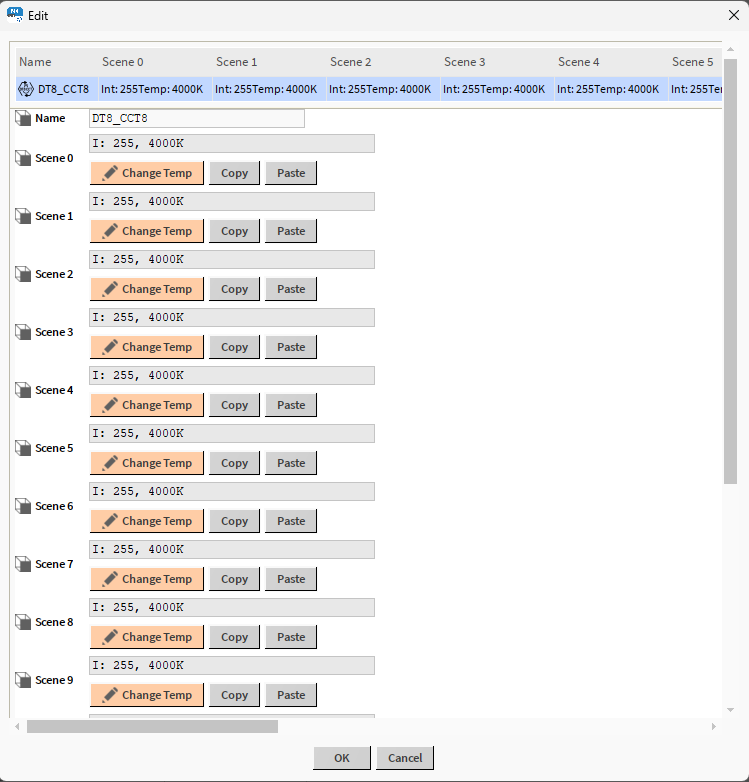
In the editing window, it is possible to change the light intensity and color temperature for each scene. To change the light intensity or color temperature, press the Change Temp button, which opens another dialog window:
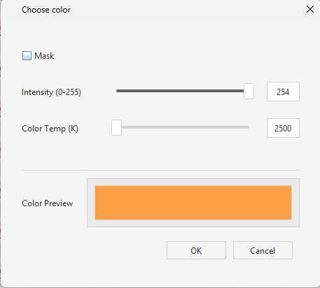
To change values, uncheck the MASK checkbox. Adjust values by moving a slider or direct value typing and confirm with OK.
The CCT scenes editing window allows to copy and paste values between scenes and between control gear devices in the Dali Scenes CCT Manager. To this end, use the Copy button on a source scene, and apply the values to another scene/control gear device with the Paste button.
Dali Scenes RGBW Manager
The Dali Scenes RGBW Manager allows to set the light intensity and red/green/blue/white color channels for DALI DT8 (Colour Control RGBW) devices.
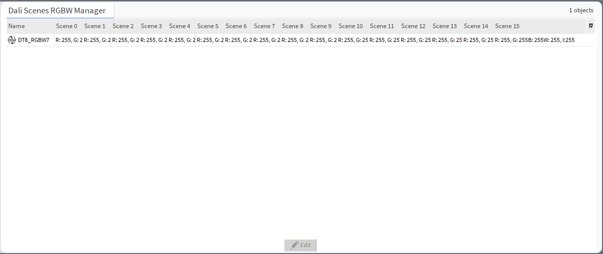
Note: Values 0-254 represent actual lighting levels and a 255 value means that when a specific scene is recalled, a device should not change its lighting level (MASK value).
Each scene value is editable by a double-click on control gear’s row. The editing dialog window pops up, where it is possible to assign the scenes' values:
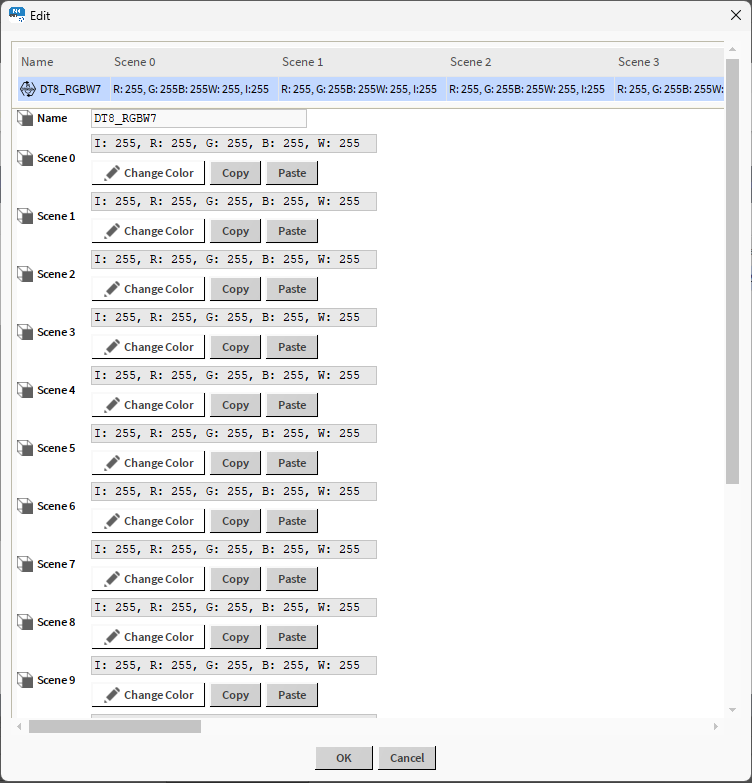
In the editing window, it is possible to change the light intensity and red/green/blue/white color channels for each scene. To change the light intensity or color channel, press the Change Color button, which opens another dialog window:
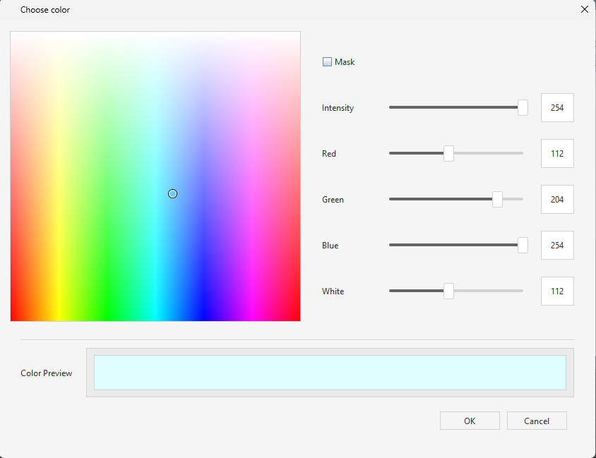
To change values, uncheck the MASK checkbox. Adjust values by a color picker, moving a slider, or direct value typing, and confirm with OK.
The RGBW scenes editing window allows to copy and paste values between scenes and between control gear devices in the Dali Scenes RGBW Manager. To this end, use the Copy button on a source scene, and apply the values to another scene/control gear device with the Paste button.
Dali Command Manager
The Dali Command Manager allows to manage all command-type components added in the Commands folder in one place.
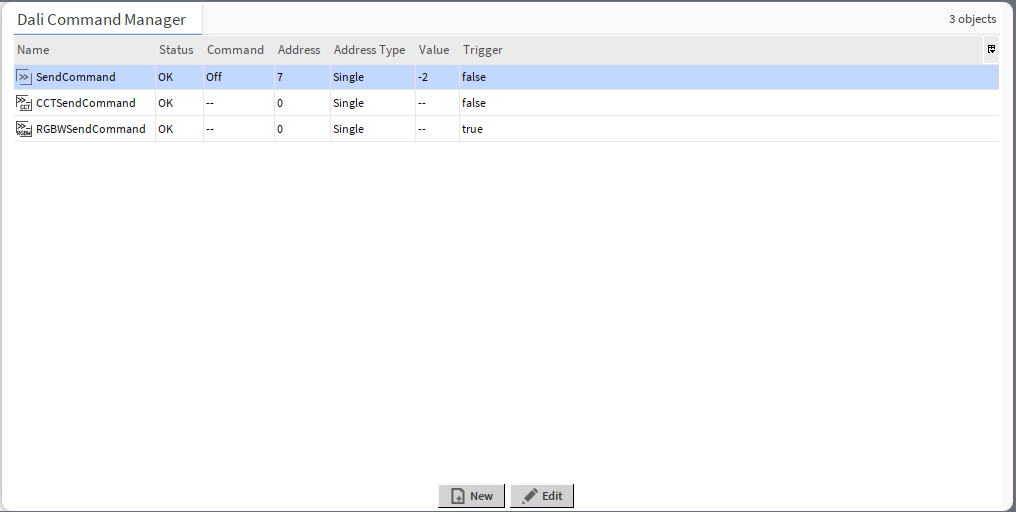
The Dali Command Manager view lists all command-type components from the Commands folder with the following data:
-
Name: shows the name of the command-type component,
-
Status: shows the status of the component,
-
Command: shows which DALI command will be executed by the trigger action,
Note: If the component is designed to execute only one type of the command, this column will be empty and not editable.
-
Address: shows a short address of the target device to send out the command to,
-
Address Type: shows the target device(s) to send out the command (single, group, all),
-
Value: shows the value of the command to send out,
-
Auto Trigger: (available from the Property Sheet view) allows to enable an auto-trigger mechanism—if set to true, a command is sent on any update to the Value slot;
-
Trigger: shows the status of the triggering action set in the component.
For each component, the Dali Command Manager has an editing action:
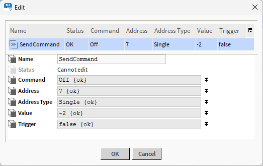
In the editing window, it is possible to change the component’s name, command (if not component-dependent), target device(s) address and address type, value, and the triggering action status.
In the Dali Command Manager, it is also possible to add a new command-type component. To this end, use the New button.
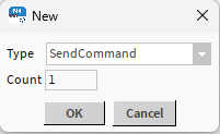
Select the type of the component (SendCommand, EncodedSendCommand, CCTSendCommand, or RGBWSendCommand) or Point Folder, and a number of components to add. Confirm with OK. The component(s) will be automatically visible in the Dali Command Manager and in the nav tree.