User Interface
Main Window
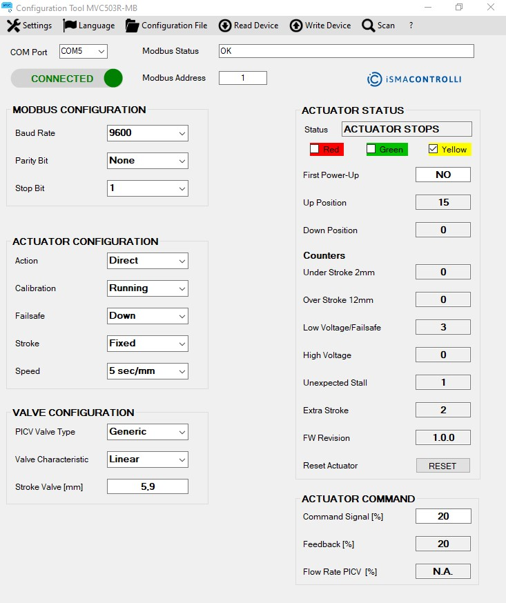
When the software is executed, the following window will be displayed:
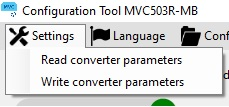
From the "Settings" menu on the top of the window is possible to select:
"Read converter parameters": read the Modbus communication parameters of the converter
"Write converter parameters": write the Modbus communication parameters in the converter (the values have to be configured in the comboboxes in the "Modbus Configuration" area).
This options allow to set the communication parameters on the PC side (master).
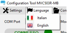
From the "Language" menu on the top of the window it will be possible to change the language of the Configuration Tool. The selectable languages are: Italian and English.
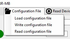
From the menu "Configuration File" it will be possible:
To load into the actuator the configuration parameters specified in the selected file (.csv format) only after the Modbus connection is successfully established ("CONNECT" button).
To save a configuration file including all the values present into the software interface (values into the areas: Actuator Configuration, Valve Configuration and Modbus parameters (baud rate, parity bit and stop bit)).
To read from the configuration file the parameters and show them into the software interface.
For the two last functions the Modbus connection with the actuator is not required.
From the "Read Device" menu on the top of the window is possible to read all information from the device.
From the "Write Device" menu on the top of the window is possible to write the configuration values into the device.

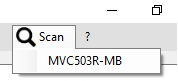
From the menu "Scan" it will be possible to perform a Modbus scan of the actuators on the network.
From the "?" menu on the top of the window is possible to know the configuration tool version.

At startup the only selectable Menus are "Language" and "Configuration File", the "Scan" menu will be enabled once the "CONNECT" button is clicked and if the connection was successful.
The available functions of the main window are:
Connection to the actuator according the MODBUS configuration parameters (MODBUS CONFIGURATION box).
Configuration of the actuator (ACTUATOR CONFIGURATION box).
Configuration of the valve characteristic (VALVE CONFIGURATION box)
Positioning of the actuator in the stroke range 0-100% and verify the position (0-100%) (ACTUATOR COMMAND box).
Verify the operating status of the actuator and possible anomalies (ACTUATOR STATUS box).
Modbus Communication
In the top area of the main window under the drop-down menu, the Modbus communication parameters can be set and verified:
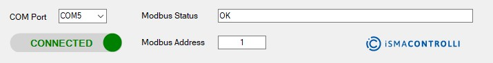
The serial port number (COM Port) which is connected the USB-RS485 converter.
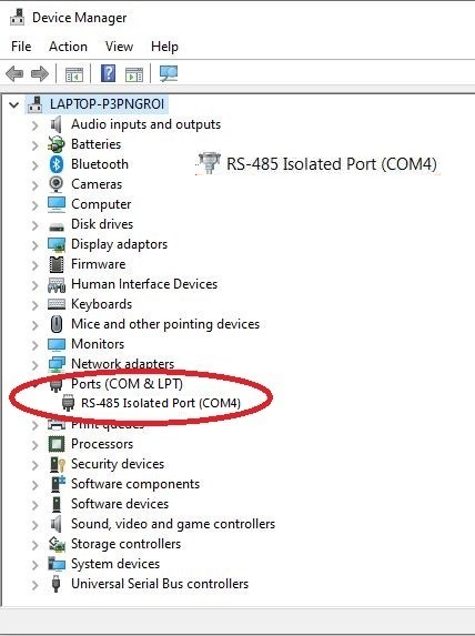
To identify the serial port number connected to the serial converter is necessary to access at the Windows Control Panel and select "Device Manager":
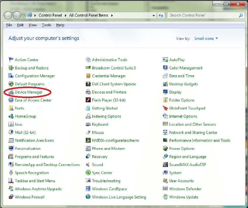
Select the field "Port (COM e LPT)" and note the serial port number related to the serial converter (in the example below: COM4).
Modbus address of the device (Modbus Address). Modbus address is selectable via the first 7 DIP switches of the actuator following the encoding into the technical manual (example to select address 1, the DIP switch n°1 has to be positioned on ON).
The modification of the Modbus address on the device is only active by switching the actuator off and on again or pressing the button "RESET" on the manager interface.
Modbus Status: shows the status of the Modbus communication and the current operation in progress.
Toggle Button (CONNECTED/DISCONNECTED): allows to connect or disconnect the serial converter. If the COM port has not been detected this button is not enable.
After press the CONNECT button verify if Modbus Status is OK. The parameters set in the Modbus Configuration box are requested only the first time the software and the Serial converter are used.
"Modbus Configuration" Box
In this box it is possible to set the Modbus configuration parameters.
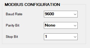
Baud Rate (selectable between 9600 and 19200)
Parity Bit (selectable between none, odd and even)
Stop Bit (selectable 1 or 2)
The default communication parameters are: 9600, No parity and 2 stop bits.
To write the configuration inside the actuator press the "Write Device" button on the top menu.
"Actuator Configuration" Box
In this box it is possible to set the following configuration parameters of the actuator:
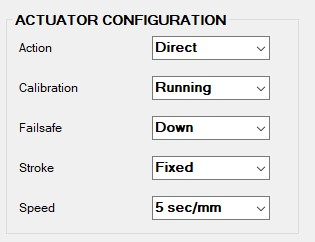
Action: it allows to select direct or reverse action
Calibration: it allows to start the stroke calibration of the actuator
Press the "READ" button to read the current status, the select from the drop-down menu the label "Learning" and press the button "WRITE". At the end of the calibration the status Running will be shown again by pressing the "READ" button.
Failsafe: it allows to select the emergency return position of the actuator selectable between "Up" or "Down".
Stroke: it allows to set the fixed stroke mode or the automatic calibration mode;
If the fixed stroke mode is selected, the stroke value has to be set in the Valve Stroke textbox and it's necessary to press the "Write Device" button in the top menu to save it.
Make sure that the other 2 parameters in the section mentioned above are the current ones otherwise the actuator settings will be overwritten.
Speed: selectable between 5 sec/mm (default) or 3 sec/mm.
Once the configuration parameters described above have been selected, press the "Write Device" button and verify with the "Read Device" button that the parameters have been correctly set.
In order to make the parameters changes active, it's necessary to reset the actuator through the "RESET".
"Valve Configuration" Box
In this box it is possible to set the following configuration parameters of the valve:
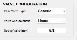
PICV Valve Type: in case the actuator is installed on a LIBRA pressure independent control valve, it is possible to select the LIBRA range from the drop-down menu in order to improve flow control.
Valve Characteristic: it allows to select the characteristic of the LIBRA valve (linear or equipercentage).
Stroke Valve [mm]: it allows to read the calibrated stroke value or select the stroke value in fixed stroke mode.
Once the configuration parameters described above have been selected, press the "Write Device" button and verify with the "Read Device" button that the parameters have been correctly set.
In order to make the parameters changes active, it's necessary to reset the actuator through the "RESET" button in the "Actuator Status" box.
"Actuator Status" Box
In this box the actuator status and possible anomalies are shown:
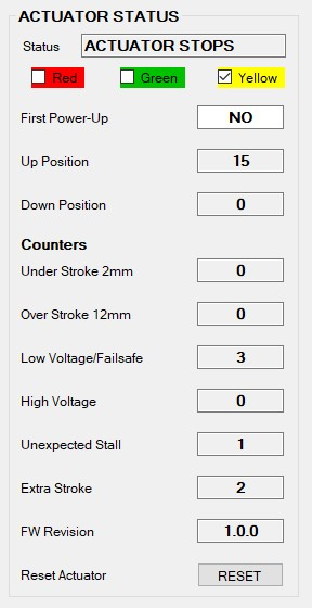
Status: it shows the current status of the actuator (initial positioning, calibrating, up end stroke, down end stroke, up positioning, down positioning) and the led status on the electronic board.
First Power-Up: it shows if the actuator has been powered on for the first time.
Up Position: it shows how many times the actuator stem was in the fully retracted position.
Down Position: it shows how many times the actuator stem was in the fully extended position.
Stroke Under 2mm: it shows a calculated actuator stroke anomaly during calibration phase (stroke below 2mm).
Stroke Over 12mm: it shows a calculated actuator stroke anomaly during calibration phase (stroke above 12mm).
Low Voltage/Failsafe: it shows the low supply voltage anomaly events as well as the number of emergency return events.
High Voltage: it shows the high supply voltage anomaly events.
Unexpected Stall: it shows the unexpected stall events, that is how many times a stall has occurred inside the range stroke.
Extra Stroke: it shows an extra stroke anomaly compared to the calculated stroke during the calibration phase (stroke out of range).
FW Version: it shows the actuator firmware version.
Reset Actuator: SW reset of the actuator is executed by pressing the "RESET" button. Before to send others commands to the actuator it is necessary to wait the supercap recharge phase is completed. In case of changes in the actuator configuration parameters, press the "RESET" button to make the changes immediately effective.
The parameters in the "Actuator Status" box are read at the connection start-up and every time the label near the textbox is clicked.
The information relating to the "Events" section can be read all 6 simultaneously by pressing the text "Counters".
"Actuator Command" Box
In this box it is possible to set the actuator position in the range of 0-100% and verify the position (feedback).
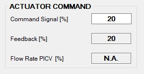
Command signal: it allows to set the modbus command for the actuator positioning in the range 0-100%.
Press "Write Device" or the "ENTER" key to send the position command to the actuator.
Feedback: allows to verify the current position of the actuator in the range 0-100%. A value of 110% indicates that the actuator is in emergency return phase, while a value of 120% indicates that the actuator is performing the initial position/calibration. The current feedback value is read by the software at the start-up and cyclically every 1.5sec (it's possible to read the value clicking on the label "Feedback"). The textbox "Flow Rate PICV" is N.A.
Flow Rate PICV: in case of "LIBRA" valve selection the percentage of the flow rate valve is shown, while the textbox "Feedback" shows N.A.
"Configuration File" Menu
This menu allows to save a .csv file useful for saving the configuration of an actuator and repeating it later on the same or on others actuators present.
In the drop-down menu are present the following items:
Load configuration file
Write configuration file
Read configuration file
*Load configuration file:* it saves into the actuator the parameters collected into the selected CSV file (make sure a valid connection is open by pressing the "CONNECT" button before loading a new configuration).
*Read configuration file:* it allows to select a configuration file and to show all the parameters in the proper textboxes.
*Write configuration file:* it allows to save the configuration file (CSV) containing all the configuration parameters.
Read and Write option can be done off-line (no Modbus connection is necessary).
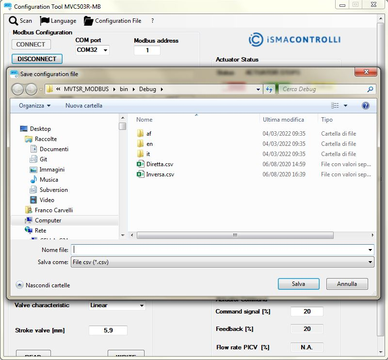
To upload directly the configuration file parameters to the actuator, select the "Load configuration file" item by selecting the desired configuration file (to perform this operation, a successful connection must be done pressing the "CONNECT" button).
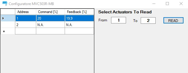
"Scan" Menu
This menu allows to perform a scan of the actuators inside the Modbus network:
The table in the left part of the windows can show the main actuator information of a subset of the actuators in the network. The scan can be executed by setting the start Modbus address and the end Modbus address of the actuator group and pressing the "READ" button.
In the following example in the Modbus network is present only 1 actuator (Modbus address 1), the one with Modbus address 2 is not present and therefore is indicated N.A. (Not Available)
Modbus Database Description
This menu allows to perform a scan of the actuators inside the Modbus network:
Address | Modbus Register | Description | Access | Persistence | Group |
|---|---|---|---|---|---|
6678 6679 6680 | Firmware version | Firmware version (composed of 3 bytes): 1st byte: major version 2nd byte: minor version 3rd byte: revision version | Read | YES | Configuration |
6681 | First power up | Represents the first power up event. After this event the value is 0xCF. | Read | YES | Configuration |
6682 | Calibration error | Represents the number of times a stroke error has occurred down the minimum allowed. Range 0-254 | Read | YES | Diagnostic/ Alarms |
6683 | Calibration error | Represents the number of times a stroke error has occurred up the maximum allowed. Range 0-254 | Read | YES | Diagnostic/ Alarms |
6684 | Low voltage anomaly | Represents the number of times a low voltage event has occurred. Range 0-254 | Read | YES | Diagnostic/ Alarms |
6685 | High voltage anomaly | Represents the number of times a high voltage event has occurred. Range 0-254 | Read | YES | Diagnostic/ Alarms |
6686 | Unexpected stalls within the race | Represents the number of times a stall has occurred within the run. Range 0-254 | Read | YES | Diagnostic/ Alarms |
6687 | Extra stroke in normal operation | Represents the number of times that an extra stroke error has occurred compared to that calculated during the calibration phase (stroke out of range). Range 0-254 | Read | YES | Diagnostic/ Alarms |
6688 | Actuator stroke | Identifies the value read by the actuator after the calibration phase. It is possible to set the stroke value but requires restarting the actuator. The value must be stored multiplied by 10. Range 20-120 (2-12mm) | Read/ Write | YES | Configuration |
6689 | Actuator setting | Direct/reverse action setting. (default: direct action (bit0=1)) | Read/ Write | YES | Configuration |
Forcing calibration phase. (default: Calibration not enabled (bit1=1)) | |||||
Emergency return direction selection (up or down). (default: down (bit2=1)) | |||||
Fixed stroke (default: fixed stroke not enabled (bit3=1) | |||||
6690 | Actuator speed | Allows you to set the speed of the actuator (207 = 5s/mm o 119 = 3 s/mm). (default: 207 = 5 s/mm) | Read/ Write | YES | Configuration |
6691 | LIBRA valve type configuration | By selecting the type of PICV LIBRA valve, the stroke value is automatically set to 4 mm and reverse action. (default: 0 = NO PICV) | Read/ Write | YES | Configuration |
6692 | Characteristic configuration of the valve (β) | It represents the characteristic of the valve (β=0 linear valve, β=1 equal percentage valve). (default: 0 = linear) | Read/ Write | YES | Configuration |
6693 | Baud rate | Represents the communication speed of the Modbus protocol (9600, 19200). (default: 9600) | Read/ Write | YES | Configuration |
6694 | Parity bit and stop bit | 2 least significant bits (bits 0 and 1): parity bit (0 = none, 1 = even, 2 = odd) bit 4: stop bit (0 = 1 stop bit, 1 = 2 stop bit) (default: 16 = none and 2 stop bits) | Read/ Write | YES | Configuration |
6146 | Opening phase | It is the number of times the actuator has been in the total opening position Range 0-65279 | Read | YES | Diagnostic/ Alarms |
6147 | Closing phase | It is the number of times the actuator has been in the total closing position. Range 0-65279 | Read | YES | Diagnostic/ Alarms |
8840 | Actuator control | Represents the percentage of control of the actuator (by setting a value between 0 and 100% it allows to drive the motor in any position). Range 0-100% | Read/ Write | NO | Input/ Output |
8841 | Actuator operating status | Represents the current operating status of the actuator (based on the status of the LEDs). Range 0-16 | Read | NO | Diagnostic/ Alarms |
8842 | Reset actuator | Allows you to perform a software reset of the actuator. Writing 1 performs a reset. (default: 0 = no reset) | Read/ Write | NO | Configuration |
8288 | Valve position (feeback) | Represents the position of the actuator. (0-1000 normal function, 1100 emergency return, 1200 calibration) (divide by 10 to have % value) | Read | NO | Input/ Output |
8289 | Valve flow rate | In the case of selection of the PICV, it represents the percentage flow rate value (the value of the feedback register is not available). Range 0-1000 (divide by 10 to have % value) | Read | NO | Input/ Output |