This section shows how to add a network, devices and points, using built-in tabular views divided into segments.
Segment 1
To add a new network (driver) to the application:
-
open a proper Driver Manager view available at app -> Drivers in the Workspace Tree;
-
drag the required driver (component) representing the proper network from the Device Kits window;
Note: To make working with drivers views (but also device and point views) easier, the iC Tool filters components available to use in the Device Kits window, leaving only the ones, which can be added to the particular view. The figure below shows the open Driver Manager view with a list of available components in the Device Kits window. The list of components has been limited to these, which define networks, e.g., ModbusAsyncNetwork, ModbusTCPNetwork, ModbusTcpSlaveNetwork, OneWireNetwork, localIO, etc. The figure below shows the process of adding a driver ModbusAsyncNetwork to the Driver Manager view.
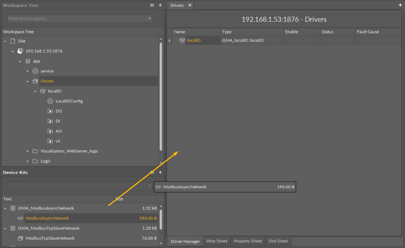
Adding a component to the Drivers view
-
adjust the necessary settings for the added network–it is best to use the Object Properties window, which shows parameters of the added driver after it has been selected, see the figure below. A basic thing to set in the beginning is to enable the network using the Enable action in the Object properties window.
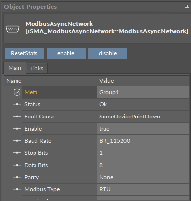
The Object Properties of an added network
Warning!
Inactive disabled drivers are marked with gray color, see the figure below.
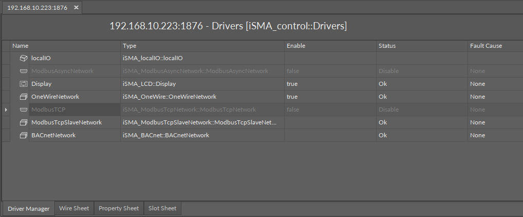
Disabled network view
Segment 2
Next, it is necessary to add the devices to the ModbusAsyncNetwork, which are part of this network:
-
double-click the added network (driver) and open the Modbus Async Device Manager view;
-
drag the components representing device types installed in this network into the view. The figure below shows dragging the component representing the iSMADevice type of device.
Note: To make working with device views easier, the iC Tool filters devices, which support the selected communications network (ModbusAsync); in the example below the devices are: ModbusDevice and iSMADevice.
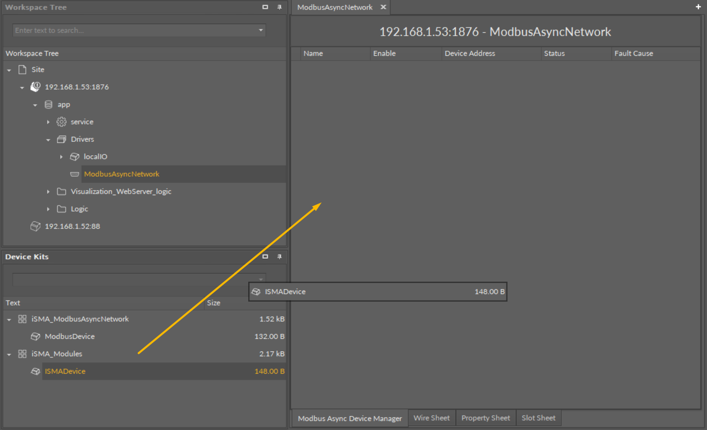
Adding a device to the network
-
configure the device settings in the Object Properties window.
COnfigure the device in the Object Properties window
Warning!
Inactive devices are indicated by gray color, as shown in the figure below. To activate a device, the Enabled slot needs to be set to true using the Object Properties window.

Disabled device view
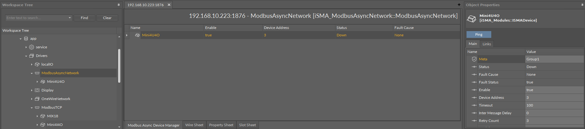
Note: Red color indicates faulty devices with Fault status, see the figure below.

Faulty devices view
Segment 3
Next, add network points to the defined device, so the application in the controller will be able to read and record data from/to an external device:
-
open the Modbus Async iSMA Module Point Manager view double-clicking the freshly added device;
This time as well, the component list in Device Kits is limited to those, which cooperate with the selected device. Besides typical read and write points (here components with N and B icons), there is also a component of another type, the ModulesFolder, see the selected folder in the figure below.
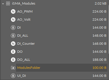
The ModulesFolder container
The ModulesFolder is a container (folder) allowing to group the network points. It may be nested in the third segment views any number of times. The figure below shows the process of adding the UI_Temp network point to the iSMA-B-4U4O device.
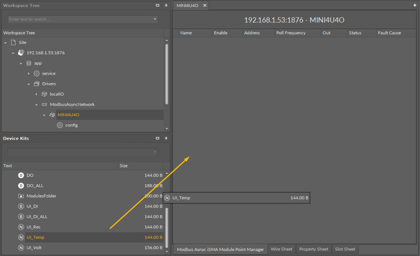
Adding a network point to the device
Warning!
To determine which device the particular network point belongs to, or which network it belongs to, the access path (figure below) is displayed above the Main window in the upper part of the screen. This dependency is also visible in the Workspace Tree.

Device and network points dependency
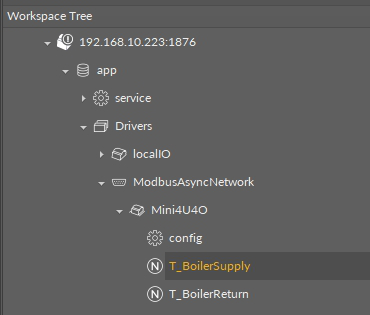
Device and network points dependency
-
configure the parameters required for each of network point separately, e.g., the address, in the Object Properties window.
Warning!
Red color indicates faulty points with ‘Fault’ status, see the figure below.

Faulty network points view
After successfully configuring the network points parameters, its device, and network, which the device works in, the current value will be read by the network point.
The process described above needs to be performed repeatedly for every network, every device in network, and all required network points.
Modbus CSV Export
For Modbus TCP and Modbus Async slave networks, an additional view is available–the Modbus Export CSV view. The view lists all points in the network with the following parameters and allows to export the list to a CSV file:
-
name;
-
description;
-
address format;
-
address;
-
information if the point writable or not;
-
data type;
-
bit number.
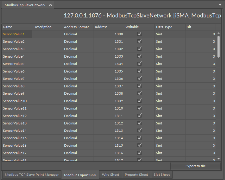
The Modbus Export CSV view
To export the list, click the Export to file button. Exported file can include all data or specific columns:
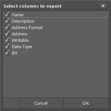
Selecting columns to export
Press OK to confirm, and the file is downloaded automatically.