Inputs
The iSMA-B-FCU device is equipped with two types of inputs: 4 digital inputs (for Boolean values) and 4 special inputs (for resistance and voltage measurement).
Special Inputs
The iSMA-B-FCU device has 4 built-in special inputs, which can work in the following modes:
-
digital (dry contact);
-
analog (0-10 V DC);
-
resistance (0-1000 kΩ (1 MΩ));
-
temperature (working with NTC sensors).
Special Input in Digital Mode
In this mode, the special input works as a digital input dry contact and reactive Boolean value, false for open circuit and true for close circuit. The circuit status is measured with 1 mA current.
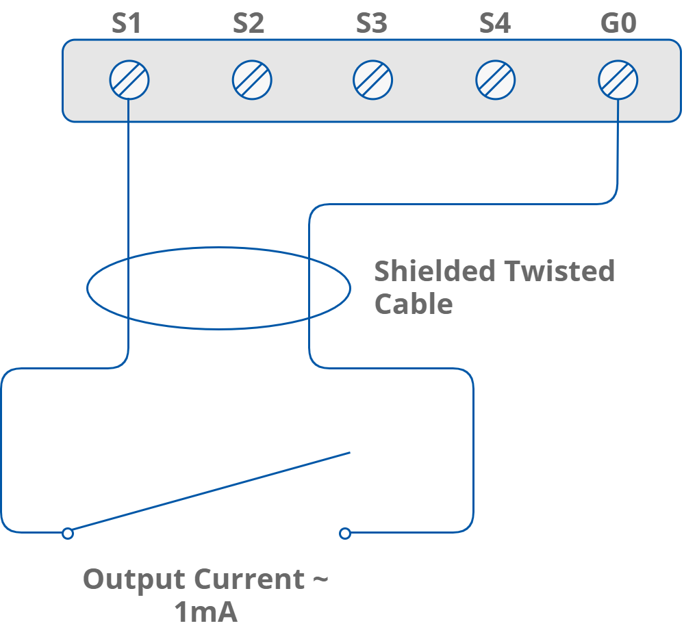
Speical inputs in digital mode connection
Special Input in Analog Mode
In this mode, the special input measures voltage in the range from 0 to 10 V DC (10 000 mV) with 6 mV resolution.
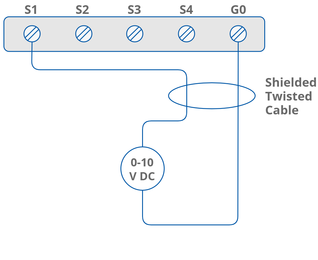
Special inputs in analog mode connection
Special Input in Resistance Mode
In this mode, the special input measures resistance value with the voltage driver. The input works in range from 0 to 1000 kΩ (1 MΩ), with resolution ±20 Ω for 20 kΩ load.
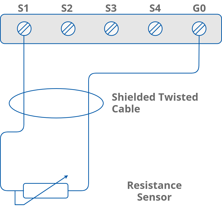
Special inputs in resistance mode connection
Special Input in Temperature Mode
In this mode, the special input measures NTC sensor resistance with the voltage driver and converts to temperature value. The special input is equipped with a built-in conversion table for the following NTC sensors:
-
10K3A1 NTC B=3975K temperature sensor;
-
10K4A1 NTC B=3695K temperature sensor;
-
10K NTC B=3435K Carel temperature sensor;
-
20K6A1 NTC B=4262K temperature sensor;
-
2K3A1 NTC B=3975K temperature sensor;
-
3K3A1 NTC B=3975K temperature sensor;
-
30K6A1 NTC B=4262K temperature sensor;
-
SIE1 temperature sensor;
-
TAC1 temperature sensor;
-
SAT1 temperature sensor.
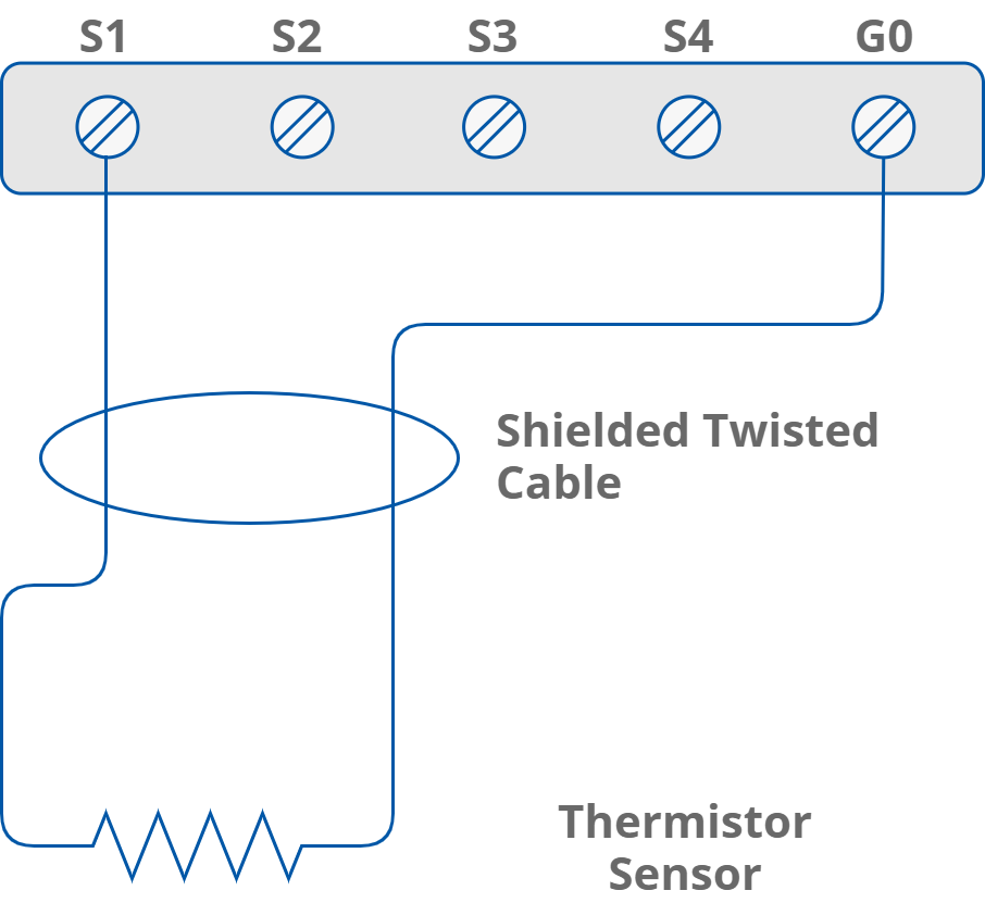
Special inputs in temperature mode connection
Digital Inputs
The iSMA-B-FCU device is equipped with 4 digital inputs. The figure below presents the way they are connected.

Digital inputs connection
Digital Input Fast Counter
The digital input can work as a counter of dry contact pulses up to 100 Hz. The counter value is saved in the non-volatile EEPROM memory.
Warning!
If the default settings are restored, the value of the counter is set to 0.
Outputs
The iSMA-B-FCU device is equipped with three types of outputs: 2 triac outputs, 5 digital outputs, and 4 analog outputs.
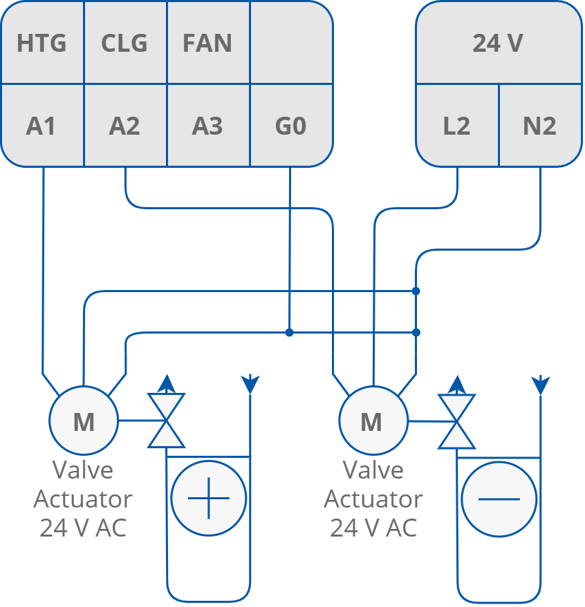
Triac Outputs
The iSMA-B-FCU device is equipped with two triac outputs designed for heating and cooling thermal valve actuators. Depending on controller model, triac outputs can be connected to actuators with 230 V AC supply (for iSMA-B-FCU-HH) or to actuators with 24 V AC supply (for iSMA-B-FCU-HL and iSMA-B-FCU-LL). In the iSMA-B-FCU-HL version, triac outputs are supplied with 24 V AC from a build-in transformer, whereas in iSMA-B-FCU-LL and iSMA-B-FCU-HH triac outputs are connected directly to power supply terminals.
Triac outputs can work as typical binary outputs (for the binary temperature control) or with PWM modulation. The PWM mode has two parameters:
-
duration time in seconds (this value depends on valve parameters);
-
fill out (percentage value of signal fill out).
The figure below presents the way actuators are connected to triac outputs (for 4-pipe mode).
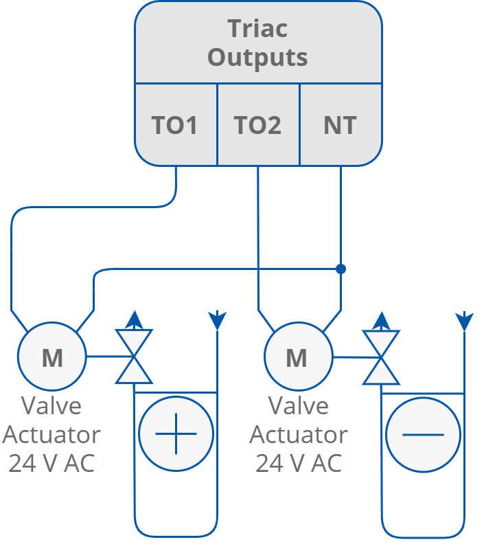
Triac outputs connection
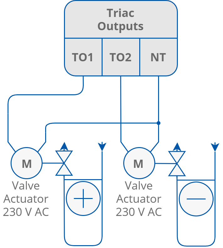
Triac outputs connection
Warning!
In case of the iSMA-B-FCU-HH or iSMA-B-FCU-LL hardware versions, the actuators connected to each triac output may consume up to 0.5 A under constant load. In some cases the current can be higher for a limited time, 1.5 A up to 30 seconds.
In case of the iSMA-B-FCU-HL controller, the sum of power consumption of both triac outputs and 24 V AC output cannot exceed 0.3 A (7 VA):
Imax = 0.3 A = ITO1 + ITO2 + I24VOut.
Digital Outputs
All digital outputs are based on relays, which can operate with 230 V AC voltage (in iSMA-B-FCU-LL, digital outputs are working with 24 V AC). The iSMA-B-FCU device has 2 types of digital outputs:
-
O1-03 and 05: relay outputs connected directly to power supply terminal;
-
O4: a relay separated from iSMA-B-FCU device circuits.
O1-O3 Fan Relays
The iSMA-B-FCU device is equipped with three relay outputs, designed for connecting up to 3 speed fans. The way the fans are connected (depending on the number of speeds) is presented in the figure below. The common terminal for those outputs is connected directly to the power supply “L” terminal.
Warning!
Outputs O1-O3 and output O5 are protected by a built-in 6 A fuse. Total current for digital relays outputs O1-03 and O5 cannot exceed 6 A.
Warning!
It is forbidden to use a fuse with current exceeding 6 A! Higher current may permanently damage device and cause danger to the user and to the equipment!
Warning!
In iSMA-B-FCU-LL, the 24 V AC fan motor is required.
The exemplary fan connection is presented in the figure below.
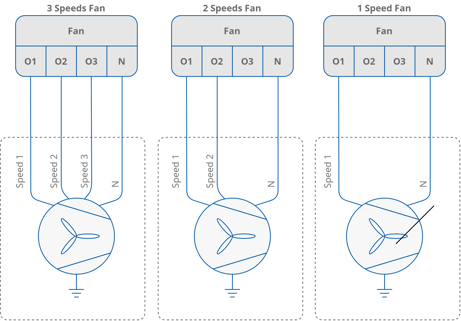
O1-O3 digital outputs, examples of conenctions
O4 HTG Relay
The iSMA-B-FCU device is equipped with relay output, which in the FCU application is dedicated to an external heater. This relay is separated from the rest of the control circuit. Current consumption cannot exceed 10 A with 250 V AC power supply. The figure below presents the way of connecting.
Warning!
HTG relay voltage is always limited to 250 V AC, irrespectively of the power supply version of the FCU controller.
Warning!
This digital output is equipped with a separate circuit with 10 A relay. This circuit requires using external fuse protection up to 10 A. The current higher than 10 A may permanently damage device and cause danger to the user and to the equipment!
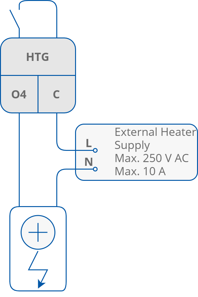
Example of an electrical heater connection
O5 CLG Relay
The iSMA-B-FCU device is equipped with a relay output, which in the FCU application is dedicated to an external cooler. This relay output is internally connected to the power supply, therefore there is no need to connect external supply. In iSMA-B-FCU-HH and iSMA-B-FCU-HL the output voltage in high state is 230 V AC, and in iSMA-B-FCU-LL version the high state voltage is 24 V AC. Current consumption cannot exceed 6 A. An exemplary way of connecting is presented in the figure below.
Warning!
Output O4 and outputs O1-O3 are protected by a 6 A fuse. Total current for digital relay outputs cannot exceed 6 A.
Warning!
It is forbidden to use a fuse with current exceeding 6 A! Higher current may permanently damage the device and cause a danger to the user and to the equipment!
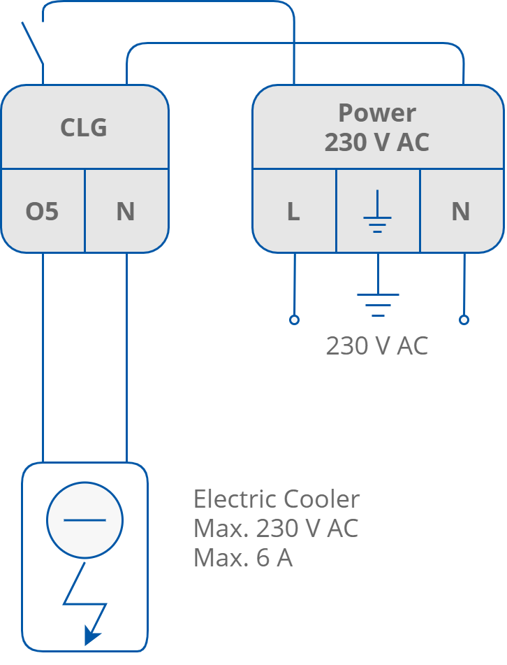
O5 digital output, example of 230 V AC electrical cooler connection (iSMA-B-FCU-HH, iSMA-B-FCU-HL)
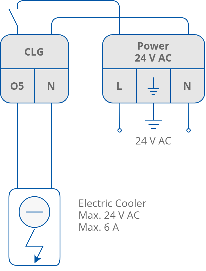
O5 digital output, example of 24 V AC electrical cooler connection (iSMA-B-FCU-LL)
Analog Outputs
The iSMA-B-FCU device is equipped with 3 analog outputs 0-10 V DC. These outputs are designed for controlling the following actuators:
-
A1 (HTG), analog heating valve actuator;
-
A2 (CTG), analog cooling valve actuator;
-
A3 (FAN), analog fan speed control.
The recommended way of connecting analog outputs is presented in the figures below.
Analog outputs, example of connecting 0-10 V analog valve actuators
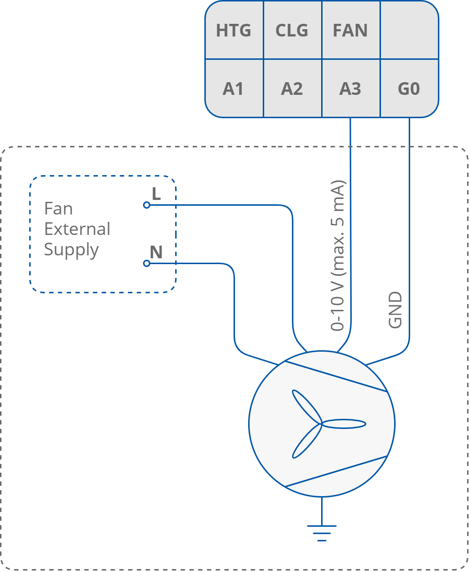
Analog outputs, example of connecting 0-10 V analog fan control