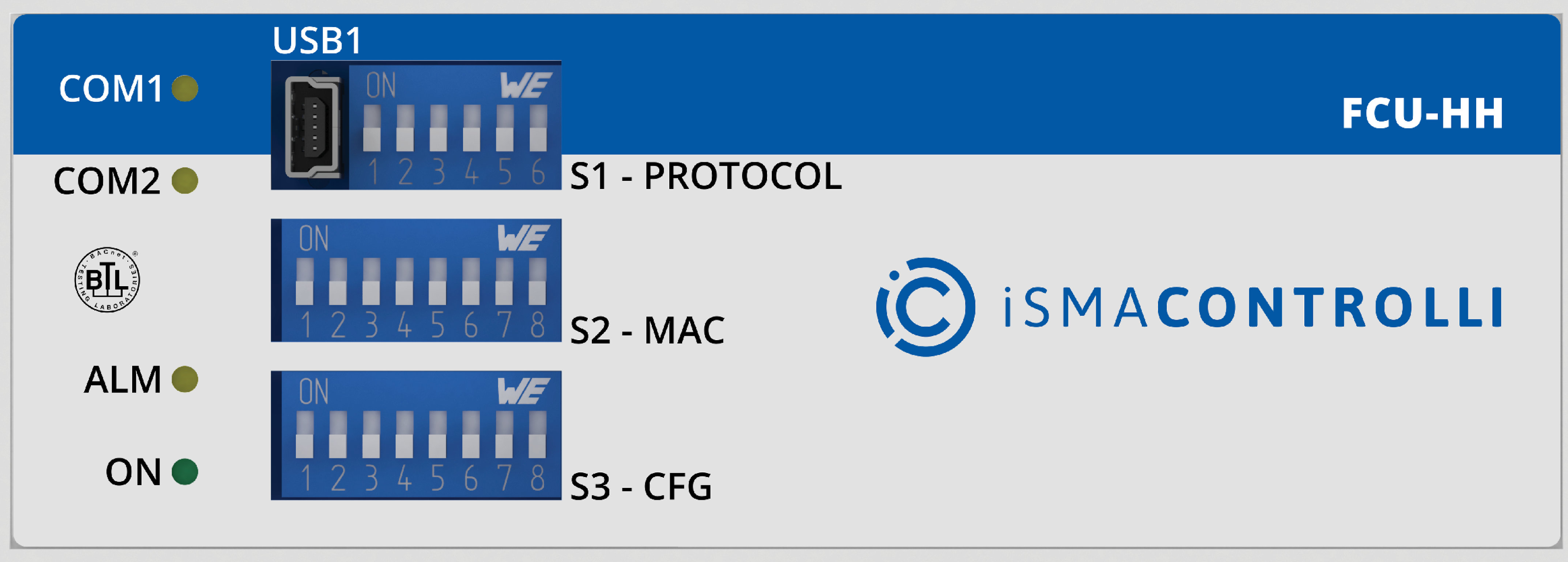
FCU front panel
USB1 Port
The iSMA-B-FCU device has a built-in mini USB1 port designed to manage controller firmware and application, as well as for diagnostics.
This USB1 port also provides controller power supply for commissioning processes and for application diagnostics. If the controller is powered up by a USB, all inputs and outputs are operational (except for triac outputs, which require external power supply).
LED
The iSMA-B-FCU device is equipped with 4 LED diodes for quick status check and diagnostics:
-
The power LED (ON) lights up (green) after turning the power on.
-
The communication LED (COM1) lights up (orange) for 20 ms after sending each package through the main RS485 port. As long as module receives/sends packages, the communication LED blinks continuously.
-
The extension communication LED (COM2) lights up (orange) for 20 ms after sending each package through the extension ports. As long as the module receives/sends packages, the extension communication LED blinks continuously.
-
The ALM LED is off by default, the function is programmable through the LED_ALARM component; it blinks very softly if there is a fault during the start-up of Sedona Virtual Machine.
-
During the device’s reset, when the 6th switch in the S1 - PROTOCOL DIP switch is on (default settings restoration mode), the power LED (ON) blinks in 300 ms time intervals. After the switch 6 is switched off, the power LED is lit permanently, and the default settings are restored.
-
If the device remains in the bootloader status, the power LED (ON) and the communication LED (COM1) blink alternatively. The communication LED keeps its functionality and blinks also after sending/receiving data packages.
DIP Switch
The iSMA-B-FCU controller is equipped with 3 DIP switches:
-
6-position S1 - PROTOCOL DIP switch;
-
8-position S2 - MAC DIP switch;
-
8-position S3 - CFG DIP switch.
S1 PROTOCOL DIP Switch: Baud Rate Selection
Transmission baud rate is determined by S1 switch (sections 1, 2, and 3 of the PROTOCOL DIP switch) in accordance with the following table.
|
1 |
2 |
3 |
Baud Rate |
|---|---|---|---|
|
Off (0) |
Off (0) |
Off (0) |
Defined by the user |
|
Off (0) |
Off (0) |
On (1) |
76800 |
|
Off (0) |
On (1) |
Off (0) |
4800 |
|
Off (0) |
On (1) |
On (1) |
9600 |
|
On (1) |
Off (0) |
Off (0) |
19200 |
|
On (1) |
Off (0) |
On (1) |
38400 |
|
On (1) |
On (1) |
Off (0) |
57600 |
|
On (1) |
On (1) |
On (1) |
115200 |
Setting baud rate
S1 PROTOCOL DIP Switch: Protocol Selection
Protocol selection is made with sections 4 and 5 of the PROTOCOL DIP switch according to the table.
|
4 |
5 |
Protocol |
|---|---|---|
|
Off (0) |
Off (0) |
Modbus RTU |
|
Off (0) |
On (1) |
Modbus ASCII |
|
On (1) |
Off (0) |
BACnet client |
|
On (1) |
On (1) |
BACnet server |
Setting protocol
Warning!
In BACnet mode, switch number 4 must be in ON(1) position, and switch number 5 decides if BACnet works in master or slave mode (please check on the above table).
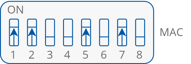
S2 MAC DIP Switch: Setting Controller Address
The controller address is set with the MAC DIP switch. The procedure of setting the address in presented in the figure and table below. The addressing table is available in the separate section.

MAC DIP switch
|
Section of MAC DIP switch |
Position |
Function |
|---|---|---|
|
1 |
On |
Add 1 to MAC address |
|
Off |
Add 0 to MAC address |
|
|
2 |
On |
Add 2 to MAC address |
|
Off |
Add 0 to MAC address |
|
|
3 |
On |
Add 4 to MAC address |
|
Off |
Add 0 to MAC address |
|
|
4 |
On |
Add 8 to MAC address |
|
Off |
Add 0 to MAC address |
|
|
5 |
On |
Add 16 to MAC address |
|
Off |
Add 0 to MAC address |
|
|
6 |
On |
Add 32 to MAC address |
|
Off |
Add 0 to MAC address |
|
|
7 |
On |
Add 64 to MAC address |
|
Off |
Add 0 to MAC address |
|
|
8 |
On |
Add 128 to MAC address |
|
Off |
Add 0 to MAC address |
Setting MAC address
Example: Configuration setting of the iSMA-B-FCU device address 83.
Address 83 contains following multiplicity of number 2: 83 = 1 + 2 + 16 + 64. Address DIP switch settings are presented in the table below. All addresses of DIP switch configuration are presented in the separate section.
|
Address |
S1 |
S2 |
S3 |
S4 |
S5 |
S6 |
S7 |
S8 |
|---|---|---|---|---|---|---|---|---|
|
83 |
On |
On |
Off |
Off |
On |
Off |
On |
Off |
Setting 83 MAC address
MAC DIP switch settings
Warning!
In BACnet network setting, the address above 128 automatically switches BACnet to slave mode. In this mode, the device cannot be discovered in device searching process.
Warning!
Do not set address 255 (all switches in ON position). This address setting is reserved for system operation.
S3 CFG DIP Switch
The iSMA-B-FCU device has the 8-position DIP switch, which can be used in client application. Each of 8 positions can have true or false state. This DIP switch is dedicated for setting configuration in client application.
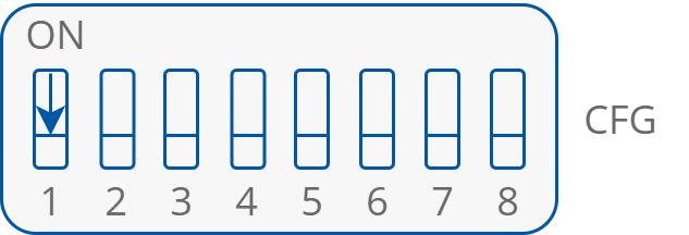
CFG DIP switch