To allow maximum comfort and energy saving as default, the application has 4 operating modes implemented. These modes are used to switch between user temperature if the space is occupied, and energy saving if the space is unoccupied/standby. There are 4 different modes:
-
occupied mode;
-
unoccupied mode;
-
standby mode;
-
forced occupied.
Each mode can be set by the following sources:
-
Room panel or digital inputs (occupancy button, presence sensor, card holder) for setting the ‘Forced Occupied’ mode only;
-
BMS using the Occupancy Mode network variable for setting any mode. The mode is changed immediately after changing the value of variable. The Occupancy Mode values and corresponding functions are presented in the table below.
The FCU occupancy modes and status with corresponding values are presented in the table below.
|
Name |
BACnet ID |
Modbus Address |
Value |
Function |
|---|---|---|---|---|
|
Occupancy Mode |
0 |
100 |
0 |
Unoccupied |
|
1 |
Occupied |
|||
|
2 |
Standby |
|||
|
Occupancy Status |
101 |
201 |
0 |
Unoccupied |
|
1 |
Occupied |
|||
|
2 |
Standby |
|||
|
3 |
Forced Occupied |
Description of Occupancy Mode and Occupancy Status network parameters
Occupancy Mode
In this mode, the controller is operating to keep room temperature set by the user.
Occupied Effective Setpoint
The Effective Setpoint is calculated based on 2 parameters, Setpoint and Offset. The Setpoint parameter defines real user room temperature value. The Setpoint Offset parameter defines the value, which user can add or subtract to the setpoint. The Offset range is limited by the Offset_Range network variable, by default to 3, therefore the user can add or subtract max. 3 degrees to Setpoint value.
Occupied Fan Control
In the occupied mode, the fan can operate with auto algorithm (see section Control algorithm), or with the user manual value. By setting the fan to the Off mode, the user can switch off device.
Occupied Heating / Cooling FCU Mode Switching
In this mode (if the FCU_Mode network variable is set to auto), the application can automatically switch between heating and cooling. The switching point is based on the Effective Setpoint and CV with Diff parameters, defined in the Heating_Cooling_Switching_Diff.
Unoccupied Mode
Unoccupied Effective Setpoint
The Effective Setpoint is calculated based on 3 parameters: Setpoint, Setpoint_Offset, and Unoccupied_Offset. In this mode, the Setpoint_Offset parameter can be disabled in Effective Setpoint calculation by Offset_In_Occupied_Only network variable. The Effective Setpoint calculation according to the FCU mode and settings is shown in table below.
|
Occupancy Mode |
FCU Status |
Offset_In_Occupied_Only |
Calculation |
|---|---|---|---|
|
0 (Unoccupied) |
Heating |
False |
Effective_Setpoint = Setpoint + Setpoint_Offset – Unnocupied_Offset |
|
0 (Unoccupied) |
Cooling |
False |
Effective_Setpoint = Setpoint + Setpoint_Offset + Unnocupied_Offset |
|
0 (Unoccupied) |
Heating |
True |
Effective_Setpoint = Setpoint – Unnocupied_Offset |
|
0 (Unoccupied) |
Cooling |
True |
Effective_Setpoint = Setpoint + Unnocupied_Offset |
Effective Setpoint in unoccupied mode calculation table
Unoccupied Fan Control
In the unoccupied mode, the fan operates in the Auto Mode, the value of which is calculated by the application. (See section 3.6.1 Fan control algorithm). In this mode, the Fan Manual Modes are disabled, and the user cannot switch off or define fan speed. If the unoccupied mode changes to occupied, the Fan Mode is switched to previous mode (Auto or user settings).
Occupied Heating / Cooling FCU Mode Switching
In this mode (if the FCU_Mode network variable is set in Auto), the application remains in the last running mode (heating or cooling) in the occupied mode. The control algorithm does not change and depends of the CFG DIP switch configuration.
Standby Mode
This mode is designed to change temperature setpoint level with a higher value in the unoccupied mode if the space is not in use for a longer time, for example, weekends or holidays. It allows to reduce energy consumption. Energy saving is done by changing the Effective Setpoint (lower for heating, increase for cooling). The Standby_Offset is bigger than Unoccupied_Offset.
Standby Effective Setpoint
The Effective Setpoint is calculated based on 3 parameters Setpoint, Setpoint_Offset and Unoccupied_Offset. In this mode, the Setpoint_Offset parameter can be disabled in Effective Setpoint calculation by Offset_In_Occupied_Only network parameter. The Effective Setpoint calculation according to FCU mode and settings is presented in the table below.
|
Occupancy Mode |
FCU Status |
Offset_In_Occupied_Only |
Calculation |
|---|---|---|---|
|
2 (Standby) |
Heating |
False |
Effective_Setpoint = Setpoint + Setpoint_Offset – Standby_Offset |
|
2 (Standby) |
Cooling |
False |
Effective_Setpoint = Setpoint + Setpoint_Offset + Standby_Offset |
|
2 (Standby) |
Heating |
True |
Effective_Setpoint = Setpoint – Standby_Offset |
|
2 (Standby) |
Cooling |
True |
Effective_Setpoint = Setpoint + Standby_Offset |
Effective Setpoint in standby mode calculation table
Unoccupied Fan Control
In the unoccupied mode, the fan is automatically switched to Auto mode and can run only with value calculated in the application. (See section 3.6.1 Fan control algorithm). In this mode, the FCU manual mode is disabled, and the user cannot switch off or define fan speed. If the unoccupied mode is changed to occupied, the Fan Mode is switched to previous mode (Auto or user settings).
Occupied Heating / Cooling FCU Mode Switching
In this mode (if the FCU_Mode network variable is set in Auto), the application stays in the last running mode (heating or cooling) in the occupied mode. The control algorithm does not change, and it depends on the CFG DIP switch configuration.
Forced Occupied
This mode is called by external devices connected to FCU digital inputs or from the room panel. This mode operates for the time defined in network parameters. The Forced Occupied behavior is the same as the occupied mode.
Switching to Forced Occupancy Mode by Occupancy Button I1
The I1 digital input is dedicated to connect presence button or sensor, which remotely runs the forced occupancy mode. This input is active only in the unoccupied or standby modes (in the occupied mode this input is inactive). If the application detects rising edge on the I1 input, it switches to the forced occupied mode. If the application detects falling edge on the I1 input, it starts counting down the time defined in the Occupancy_Time_Remote_Trigger network variable. During that time, the application is in the forced occupied mode, and the user cannot switch it off before the time elapses. After the defined time elapses, the application returns to the previous mode, unoccupied or standby. By changing the I1_Remote_Occ_Trigger_Invert network variable, the application can be connected to the devices with normal open NO or normal close NC outputs. The function time chart is presented in the figure below.

Occupancy trigger time function
Switching to Forced Occupancy Mode with Digital Input I2
The I2 digital input is dedicated to connect the presence button or card holder, which remotely run forced occupancy mode. This input is active only in the unoccupied or standby modes (in the occupied mode this input is inactive). If the application detects rising edge on the I2 input, it switches to the forced occupied mode. If the application detects falling edge on the I2 input, it starts counting down the time defined in the Occupancy_Time_Presence_Sensor network variable. During that time, the application is in the forced occupied mode, and the user cannot switch it off before the time elapses. After defined time elapsed, the application returns to the previous mode, unoccupied or standby. By changing the I2_Presence_Sensor_Invert network variable the application can be connected to the devices with normal open NO or normal close NC outputs. The function time chart is presented in the figure below.
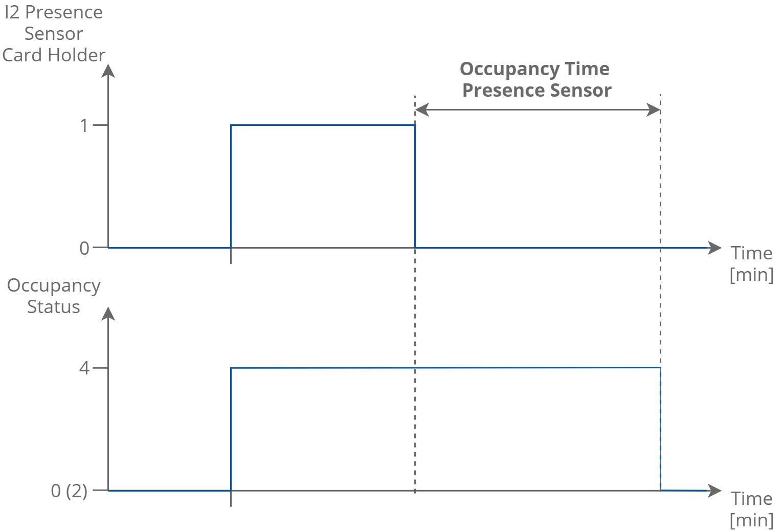
Presence sensor or card holder function time
Switching to Forced Occupancy by Room Panel (iSMA-B-LP/Touch Point)
The FCU default application is designed to work with the iSMA-B-LP and Touch Point room panels. In the panel menu, user can switch from the unoccupied or standby mode to forced occupied for the time defined in the Occupancy_Time_Remote_Trigger network parameter. The forced occupied mode is shown as a flashing occupied icon. From the room panel, the user can switch off the forced occupied and come back to the previous mode.