DigitalInputs
The DigitalInputs component is a bulk component to service all digital inputs (or inputs working in the digital mode) in the devices covered in the iClib.

The DigitalInputs component
The DigitalInputs component has the following slots:
-
In: a 24-bit numeric value representing Di1-Di12 inputs of the iSMA-B-MAX module or Di1-Di16 and Ui1-Ui8 inputs of other families and depending on the Max Device slot value:
-
if the Max Device slot is true:
first 12 bits (0x000FFF mask) transfer values to the Di1-Di12 slots; -
if the Max Device slot is false:
first 16 bits (0x00FFFF mask) transfer values to the Di1-Di16 slots;
17-24 bits (0xFF0000 mask) transfer values to the Ui1-Ui8 slots;
-
-
In2: a 12-bit numeric value representing bits of the iSMA-B-MAX device Di13-Di24 digital inputs;
Note: The In2 slot is active only if the Max Device slot is true.
-
Di1-Di12: slots of 1-12 digital inputs channels;
-
state of first 12 bits of the In slot;
-
-
Di13-Di16: slots of 13-16 digital inputs channels;
-
state of 13-16 bits of the In slot if the Max Device slot is false;
-
state of 1-4 bits of the In2 slot if the Max Device slot is true;
-
-
Di17-Di24: slots of 17-24 digital inputs channels;
-
state of 5-12 bits of the In2 slot if the Max Device slot is true;
-
-
Ui1-Ui8: slots of 1-8 universal inputs working as digital inputs channels;
-
state of 17-24 bits of the In slot if the Max Device slot is false;
-
-
Max Device: allows to change a control algorithm between the one specific for the iSMA-B-MAX module and others devices.
Worth to notice:
For the iSMA-B-MAX device, the In slot needs to be linked from the Modbus register value configured as an integer (16-bit) value (decimal: 15), and the In2 slot needs to be linked from the Modbus numeric value configured as an integer (16-bit) value (decimal: 215).
For devices equipped only with digital inputs, the In slot needs to be linked from the Modbus numeric value configured as an integer (16-bit) value (decimal: 15).
For devices equipped only with universal inputs only or with digital inputs and universal inputs, the In slot needs to be linked from the Modbus numeric value configured as a long (32-bit) value (decimal: 15).
DigitalOutputs
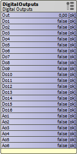
The DigitalOutputs component is a bulk component to service all digital outputs (or outputs working in the digital mode) for devices covered in the iClib.

The DigitalOutputs components
The DigitalOutputs component has the following slots:
-
Out: 24-bit numeric value representing Do1-Do16 and Ao1-Ao8 outputs:
-
firsts 16 bits (0x00FFFF mask) are affected by state of DI1-DI16 slots.
-
17-24 bits (0xFF0000 mask) are affected by state of AO1-AO8 slots
-
-
Do1-Do16: slots of 1-16 digital outputs channels (transferring values to first 16 bits of the Out slot);
-
Ao1-Ao8: slots of 1-8 analog outputs working as digital outputs channels (transferring values to 17-24 bits of the Out slot).
Worth to notice:
For devices equipped only with digital outputs, the Out slot needs to be linked to the Modbus numeric value configured as an integer (16-bit) value (decimal: 17).
For devices equipped only with analog outputs or digital outputs and analog outputs, the Out slot needs to be linked to the Modbus numeric value configured as a long (32-bit) value (decimal: 17).
ModbusClientStringWritable
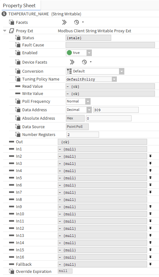
The ModbusClientStringWritable component is a network point that writes and reads 2 ASCII characters in one Modbus register. It is required to send up to 4 characters of the main menu to the iSMA-B-LP device.

The ModbusClientStringWritable component
