Web Server
By default, the AHU application is not set to autologin to the web server. To log in to the AAC20 web server, insert the IP address of the AAC20 controller in the Internet browser's address bar and confirm with Enter. Log in using the default admin credentials:
or log in using default end user (lower level of permissions than the service user - no possibility to change configuration, only setpoints) credentials;
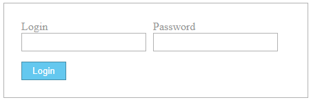 Login window Remember to copy necessary web server files to the controller's SD card (files from the selected AHU application example\Generation Output Files folder folder) and flash memory (index.html) in order for the web server to work properly. More on using the AAC20 web server is available in the Visualization Web Server user manual. |
From the downloaded and extracted archive, copy all files the selected AHU application example\Generation Output Files folder, directly to main level tree of the SD card (do not create folders or subfolders to locate the files there).
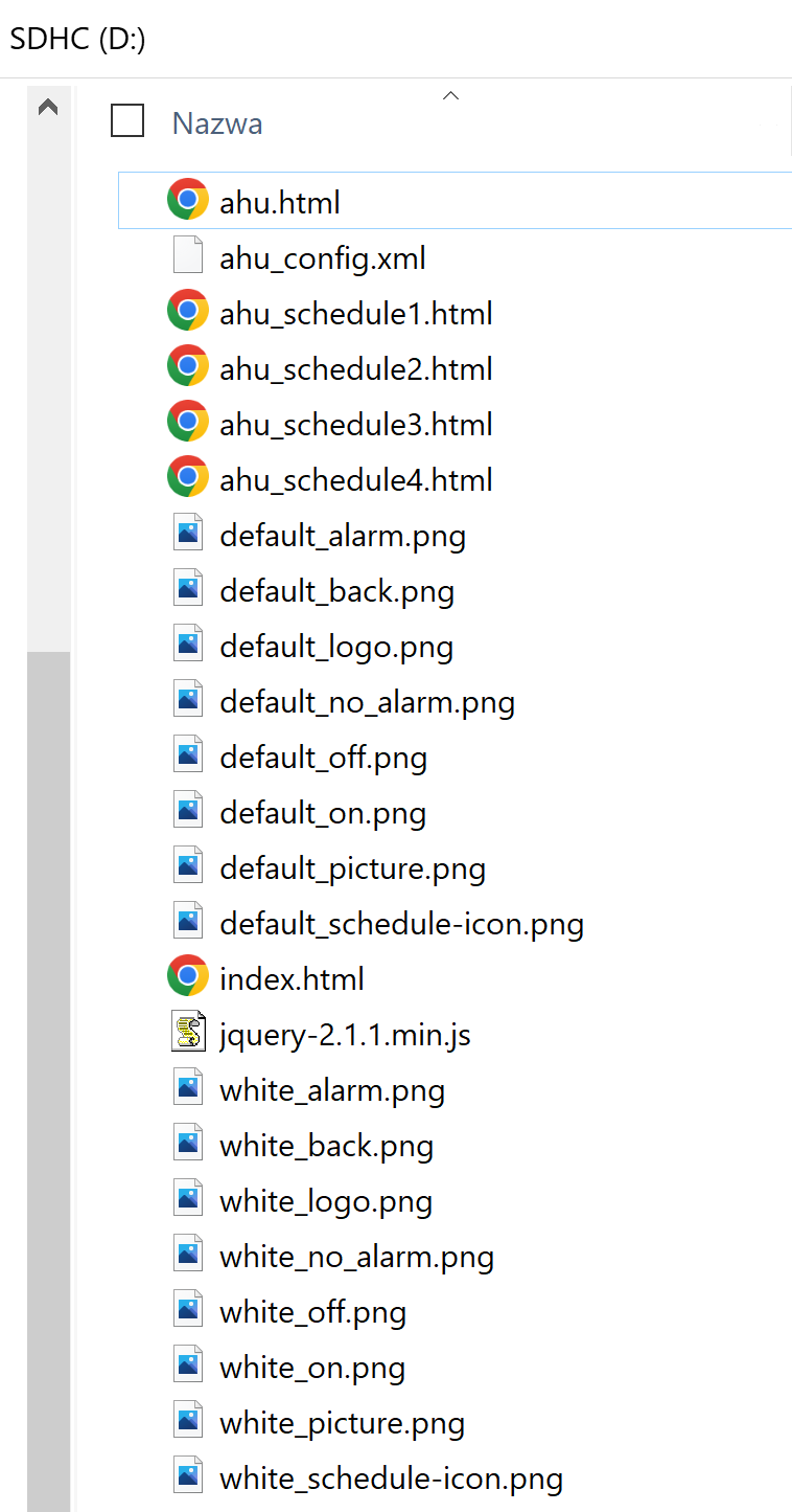
Files to copy from the selected AHU application example/Generation Output Files folder
It is also required to upload the index.html file from the web server folder of the archive to the AAC20 flash memory using the AAC20 Updater. In order to upload the index.html file, make sure that the Modbus TCP communication is active and type a correct IP address and port number if different than the default. To choose the index.html file, click the Select File button, and then send it to the device with the Send File button.
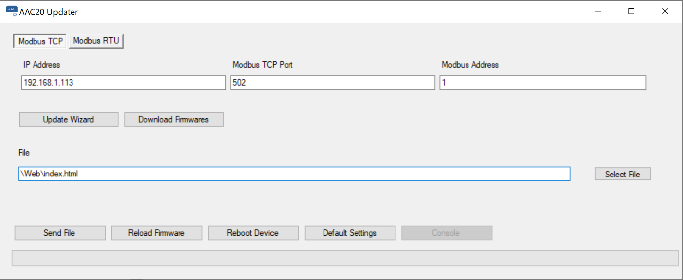
AAC20 Updater
More information on how to run the web server can be found in the AAC20 Visualization Web Server user manual.
Now, the application is ready for configuration.
Typically, the web configuration is intended for integrators, enabling to configure the application for a specific model of the air handling unit.
For the user's convenience, as well as to limit an access to configuration parameters, ready-made website templates have been prepared for the sample applications of air handling units described in the next chapter.
Ready templates are archived and placed in the main folder with files for the web server (Visualization web server files) described as ahu1.zip to ahu8.zip, where the numbering is consistent with the described examples.
In addition, separate configuration files have been prepared in order to be able to change names or translate to a language other than English. As in the case of the web file archive, the configuration files have the same numbering from Visualization_configurator_ahu1.xlsm to Visualization_configurator_ahu8.xlsm. Appropriate synoptic graphics were also prepared with the same numbering from picture1.png to picture8.png.
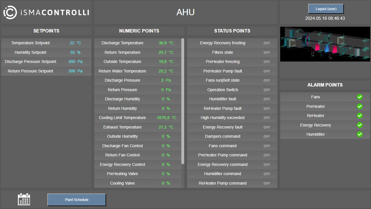
The web server for the AHU application is based on the default AAC20 web server configuration. In the web server, it is possible to configure the AHU application for a selected model of ventilation system, but also to set setpoints values, and monitor input and output signals along with alarm states.
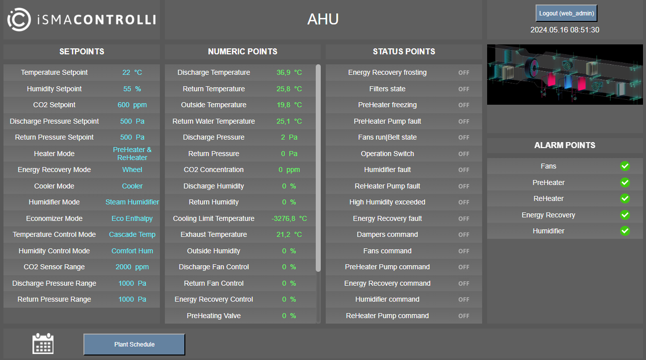
The web server for the AHU application example no. 5 - intergrator view (admin login)
Identically like in the default web server, the screen is divided into 4 columns as presented above:
Setpoints (the only column including editable points);
Numeric Points (read-only);
Status Points (read-only);
Alarm Points (read-only).
Setpoints
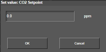
In order to edit elements available in this column, and therefore configure parameters available here, double-click a relevant point, and an editable pop-up window appears:
The Setpoints column, starting from the top, contains first the setpoints for:
temperature;
humidity;
CO2;
discharge pressure;
return pressure.
Then, relevant configuration points are available:
heater mode;
energy recovery mode;
cooler mode;
humidifier mode;
economizer mode;
temperature control mode;
humidity control mode.
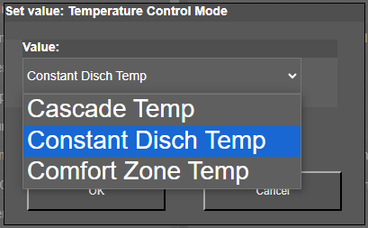
Values available for the temperature control mode
Note: Settings of the above modes are described in detail in the next section.
At the end of the list in the Setpoint column, there are points for configuration of ranges for voltage sensors such as:
CO2;
discharge pressure;
return pressure.
It has been assumed that the humidity sensors are also of voltage type in range of 0-100% for 0-10 V DC, by default.
Recommended setpoint vaules
Recommended setpoints range for the AHU application to function properly:
Temperature setpoint: 13°C-30°C
Humidity setpoint: 30% RH-70% RH
CO2 setpoint: 300 ppm-1500 ppm
Discharge pressure setpoint: 0 Pa-10000 Pa
Return pressure setpoint: 0 Pa-10000 Pa
Numeric Points
The Numeric Points column contains all numerical inputs and outputs, divided first into inputs and then into outputs. It includes inputs and outputs for the AAC20 controller with the MINI/MIX extension modules.
In the column, all monitored inputs are listed (here along with an annotation of the source device, AAC20 controller or extension I/O module):
Discharge Temperature [AAC20];
Return Temperature [AAC20];
Outside Temperature [AAC20];
Return Water Temperature [AAC20];
Discharge Pressure [AAC20];
Return Pressure [AAC20];
CO2 Concentration [AAC20];
Discharge Humidity [4U4A-H, MIX18];
Return Humidity [4U4A-H, MIX18];
Cooling Limit Temperature [MIX18];
Exhaust, Mixing or Medium Temperature [MIX18];
Outside Humidity [MIX18].
Then, a list of monitored outputs (here along with an annotation of the source device):
Discharge Fan Control [AAC20];
Return Fan Control [AAC20];
Energy Recovery Control [AAC20];
PreHeating Valve [AAC20];
Cooling Valve [AAC20];
ReHeating Valve [4U4A-H, MIX18];
Humidifier Control [4U4A-H, MIX18].
Lastly, the list is concluded with an information point about the operating mode of the ventilation system:
Plant Mode.
Status Points
The Status Points column contains all digital inputs and outputs, divided first into inputs and then into outputs. It includes inputs and outputs for the AAC20 controller with the MINI/MIX extension modules.
In the column, all monitored inputs are listed (here along with an annotation of the source device, AAC20 controller or extension I/O module):
Energy Recovery frosting [AAC20];
Filters state [AAC20];
PreHeater freezing [AAC20];
PreHeater Pump fault [AAC20];
Fans run or Fan Belt state [AAC20];
Operation Switch [AAC20];
Humidifier fault [4U4A-H, MIX18];
ReHeater Pump fault [4U4A-H, MIX18];
High Humidity exceeded (hygrostat) [MIX18];
Energy Recovery fault [MIX18].
Then, a list of monitored outputs (here along with an annotation of the source device, AAC20 controller or extension I/O module):
Dampers command [AAC20];
Fans command [AAC20];
PreHeater Pump command [AAC20];
Energy Recovery command [AAC20];
Humidifier command [4U4A-H, MIX18];
ReHeater Pump command [4U4A-H, MIX18].
Alarm Points
The last column informs about alarm states (displayed collectively) that might occur in devices controlled by the AHU application. The list of collective alarms is presented below (here along with an annotation of the source device, AAC20 controller or extension I/O module):
Fans [MIX18];
PreHeater [MIX18] (same output as for reheater);
ReHeater [MIX18] (same output as for preheater);
Energy Recovery [MIX18];
Humidifier [MIX18].
Plant Schedule
In addition, the application supports a schedule that allows to control various operating plant modes as events of the ventilation system in time. The available operating plant modes are described later in this manual. Access to the schedule is the same as the default web server, using the Plant Schedule 1 button. Setting of hours and events is the same as in the default web server. The below example shows a configured schedule.
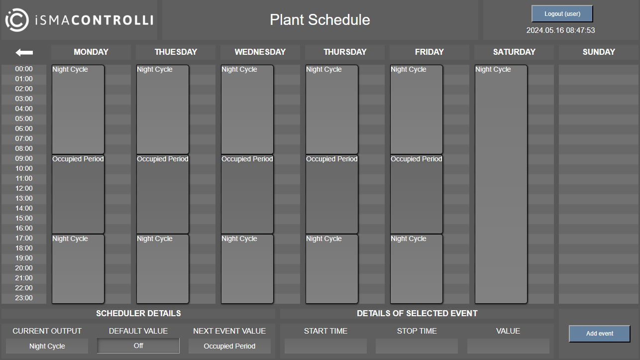
Schedule in the web server
User View
The below example is dedicated for application no. 5 in version for the end user, which has access to setpoints, but it is not possible to change the configuration from the web server level.
It also can read inputs, outputs of the controller (along with the module, depending on the configuration) and a graphical thumbnail of the air handling unit that the application supports.
The web server for the AHU application example no. 5 - user view (user login)