LCD
To use the LCD display in the AAC20 controller, there are 6 dedicated keys:
To log in to the AHU application in the AAC20 controller (to switch between users with different authorization levels) using the LCD display, follow these steps:
More on using the AAC20 controller with an LCD display is available in the AAC20 LCD User Manual. |
Apart from supporting the AHU application in the web server, it is also possible to configure it using the LCD display. The LCD display for the AHU application has been categorized in 5 folders:
Inputs (numeric and digital);
Outputs (numeric and digital);
Setpoints;
Config (visible only for the user with appropriate permissions);
Schedule.
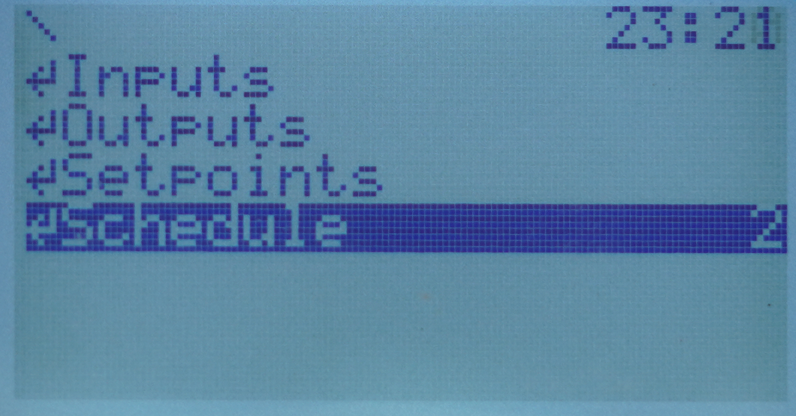
Folders on LCD
Access to the Inputs, Outputs, Setpoints, and Schedule folders does not require any authorization (the LCD service automatically uses the privileges of the default user - lcd).
Inputs
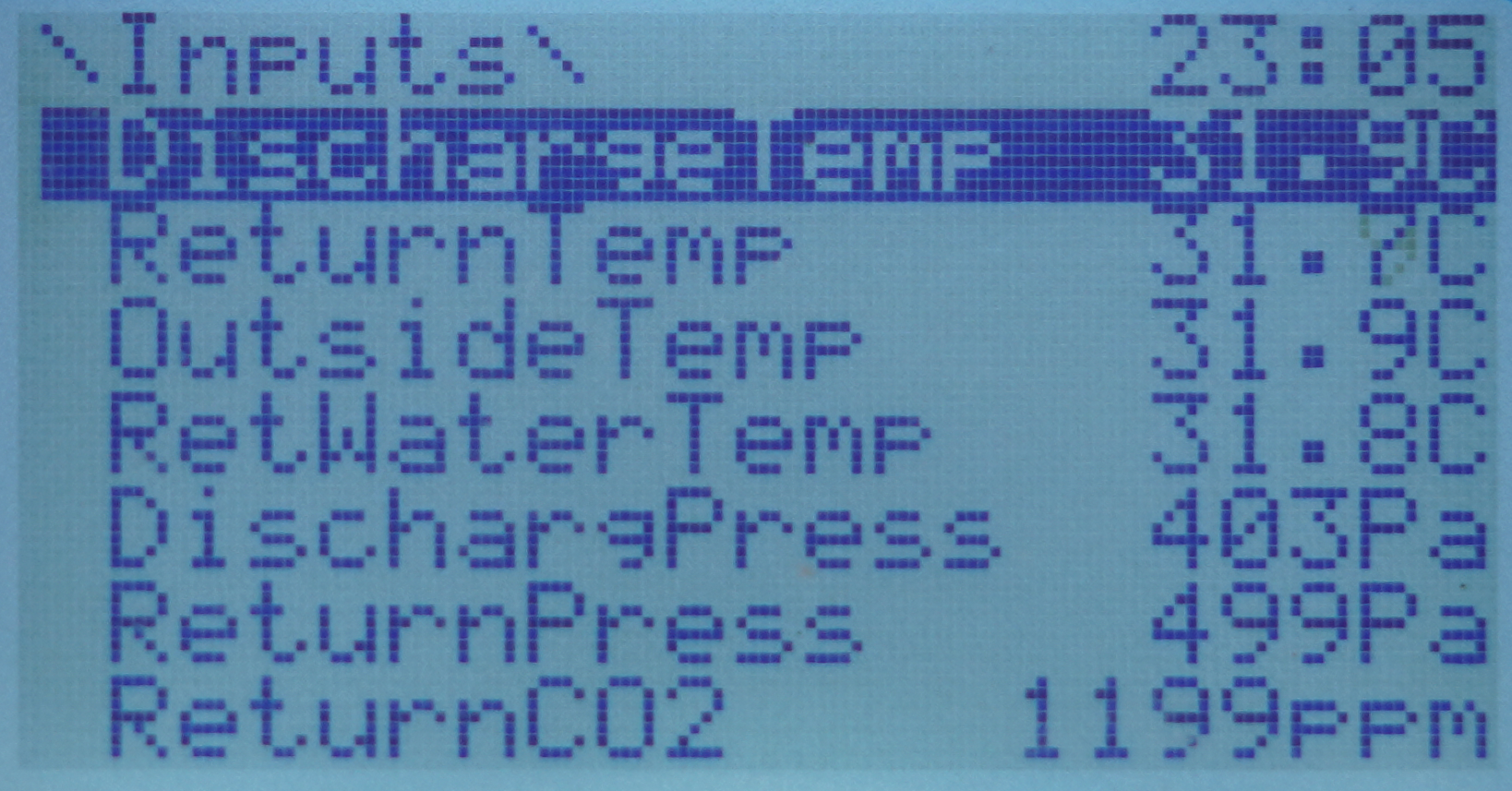
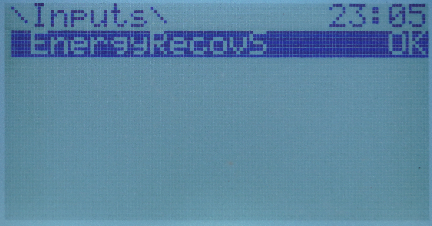
In the Inputs folder, the listed inputs are grouped first numerically, then digitally. To move to next screens/variables, use the up/down arrow buttons.
Inputs in the folder
Inputs in the folder
Inputs in the folder
Inputs in the folder
The list of numeric inputs (here with an annotation of the source device, AAC20 controller or extension I/O module):
DischargTemp: discharge temperature [AAC20];
ReturnTemp: return temperature [AAC20];
OutsideTemp: outside temperature [AAC20];
RetWaterTemp: return water temperature [AAC20];
DischargPress: discharge pressure [AAC20];
ReturnPress: return pressure [AAC20];
ReturnCO2: return CO2 concentration [AAC20];
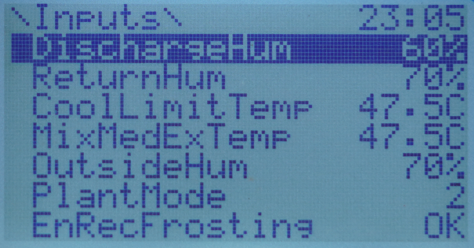
DischargeHum: discharge humidity [4U4A-H or MIX18];
ReturnHum: return humidity [4U4A-H or MIX18];
CoolLimitTemp: cooling limit temperature [MIX18];
ExMedMixTemp: exhaust or medium, or mixing temperature (depending on configuration using) [MIX18];
OutsideHum: outside humidity [MIX18].
In addition, there is a variable informing about the operating mode of the ventilation system:
PlantMode: plant mode [virtual variable].
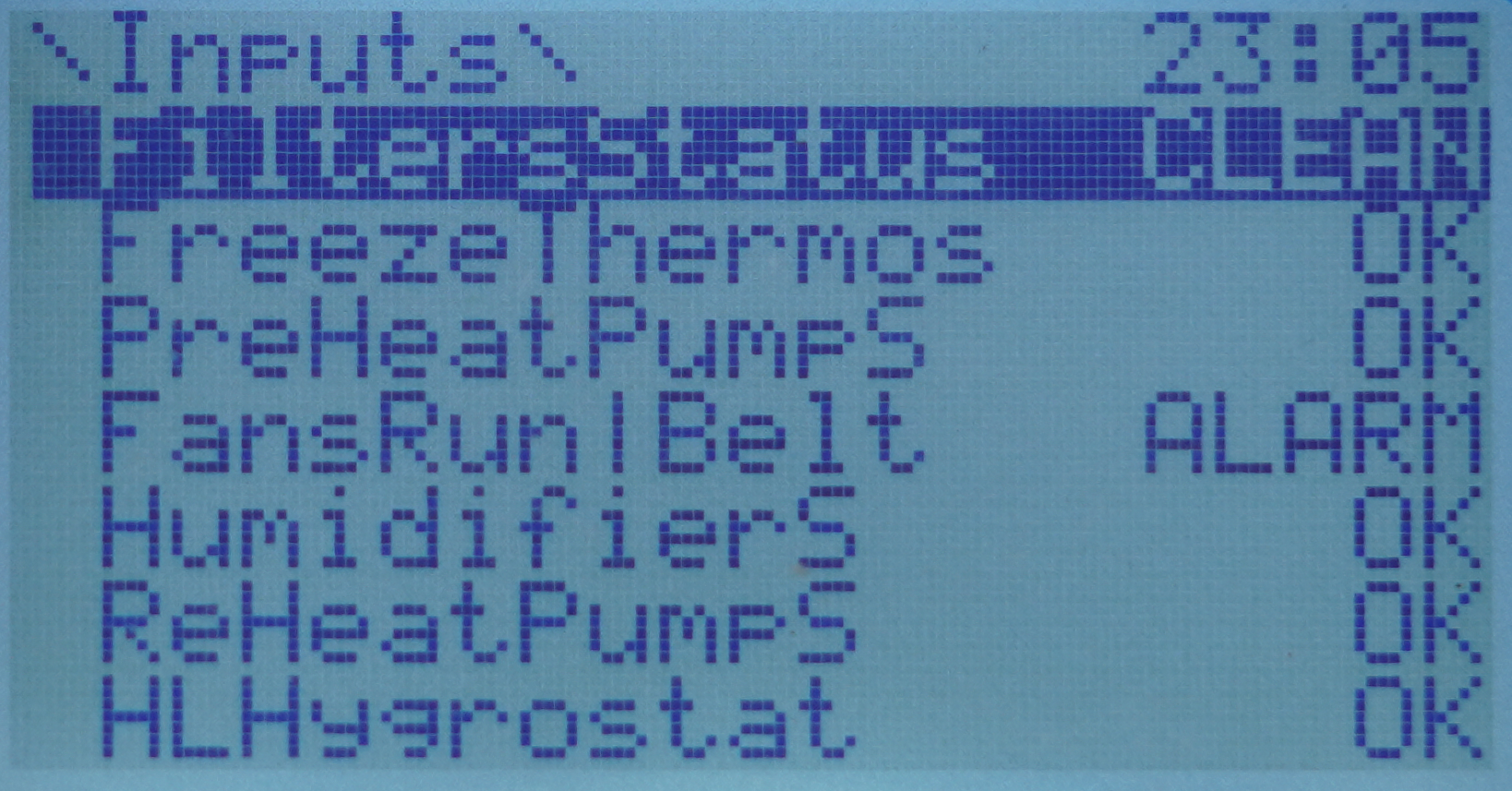
Following, the digital inputs are listed (here with an annotation of the source device, AAC20 controller or extension I/O module):
EnRecFrostion: energy recovery frosting status [AAC20];
FiltersStatus: filters status [AAC20];
FreezeThermos: freeze thermostat status [AAC20];
PreHeatPumpS: preheating pump status [AAC20];
FansRun|Belt: fans run or fans belt status [AAC20];
HumidifierS: humidifier status [4U4A-H or MIX18];
ReHeatPumpS: reheating pump status [4U4A-H or MIX18];
HLHygrostat: high limit hygrostat status [MIX18];
EnergyRecovS: energy recovery status [MIX18].
Outputs
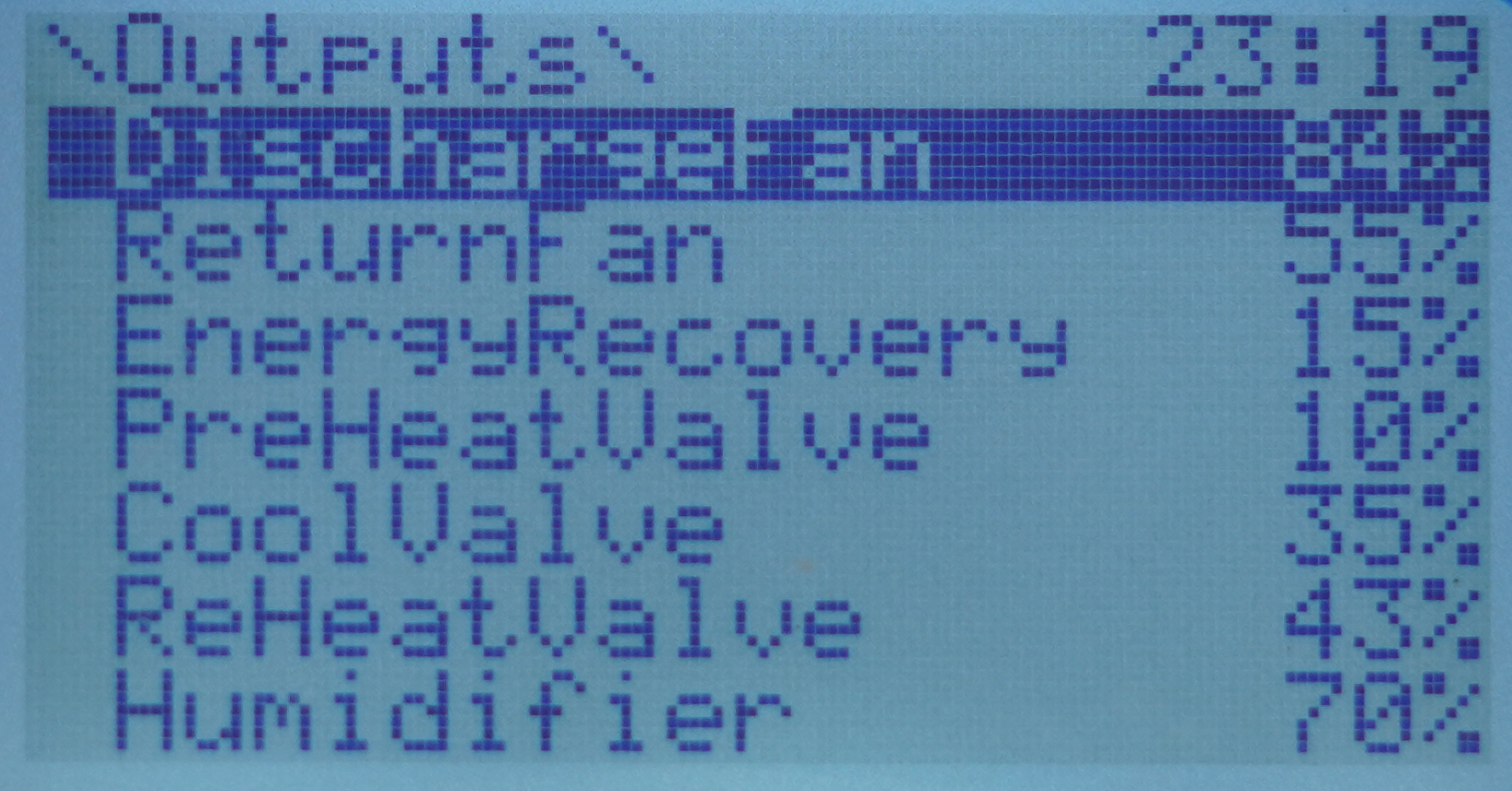
Similarly to the Inputs folder, outputs have also been arranged in the following order - first the numeric outputs, then the digital ones.
Outputs in the folder
Outputs in the folder
Outputs in the folder
The list of numeric outputs (here with an annotation of the source device, AAC20 controller or extension I/O module):
DischargeFan: discharge fan control [AAC20];
ReturnFan: return fan control [AAC20];
EnergyRecovery: energy recovery control [AAC20];
PreHeatValve: preheating Valve Control [AAC20];
CoolValve: cooling valve control [AAC20];
ReHeatValve: reheating valve control [4U4A-H or MIX18];
Humidifier: humidifier control [4U4A-H or MIX18].
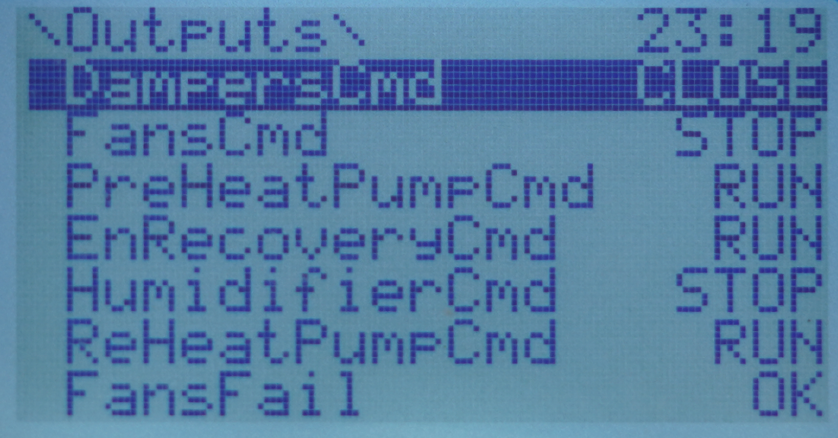
Following, the digital outputs are listed (here with an annotation of the source device, AAC20 controller or extension I/O module):
DampersCmd: dampers command [AAC20];
FansCmd: fans command [AAC20];
PreHeatPumpCmd: preheater pump command [AAC20];
EnRecoveryCmd: energy recovery command [AAC20];
HumidifierCmd: humidifier command [4U4A-H or MIX18];
ReHeatPumpCmd: reheater pump command [4U4A-H or MIX18];
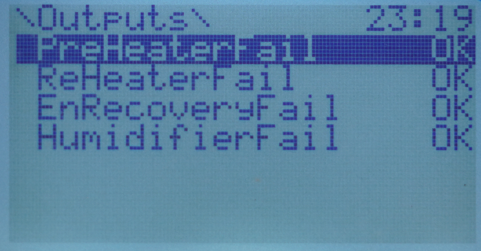
FansFail: fans failure alarm [MIX18];
PreHeaterFail: preheater failure alarm [MIX18];
ReHeaterFail: reheater failure alarm [MIX18];
EnRecoveryFail: energy recovery failure alarm [MIX18];
HumidifierFail: humidifier failure alarm [MIX18].
Setpoints
Next, it is the Setpoints folder containing settings intended for the end user.
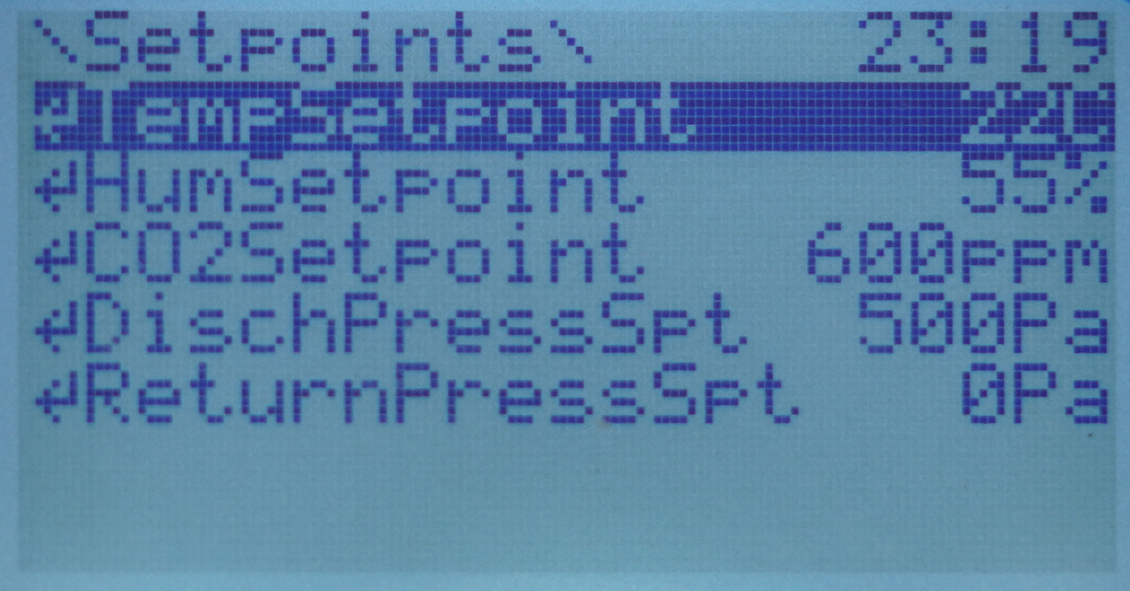
Points in the Setpoints folder
In the Setpoints folder, there are basic settings of the ventilation system, as listed below:
TempSetpoint: temperature setpoint;
HumSetpoint: humidity setpoint;
CO2Setpoint: CO2 concentration setpoint;
DischPressSpt: discharge pressure setpoint;
ReturnPressSpt: return pressure setpoint.
Config
For the Config folder to be visible and available on LCD display, log in from the LCD panel level (as described in the beginning of this section) with the user with appropriate permissions.
From the list of users, select the lcd_admin user (available: admin, lcd, lcd_admin). The default login password is 4321, which can be changed as needed by logging into AAC20 using iC Tool.
After correct logging in, go to the Config folder and the configuration parameters contained therein.
In the Config folder, there are configuration parameters of the AHU application that allow it to be configured as required by a given ventilation system.
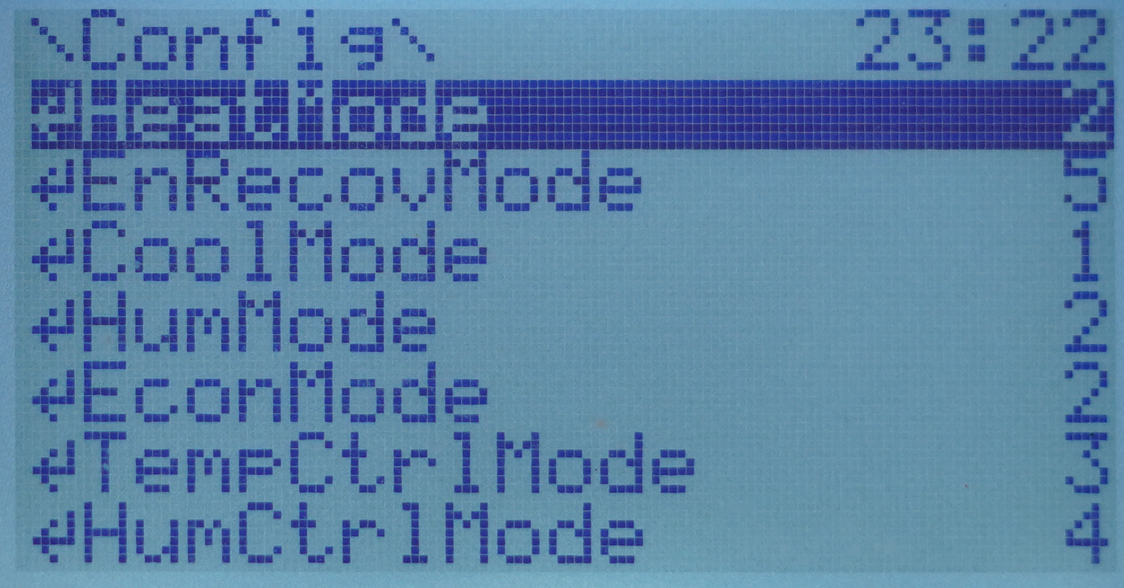
Points in the Config folder
The available configuration parameters are as follows:
HeatMode: heater mode;
EnRecovMode: energy recovery mode;
CoolMode: cooler mode;
HumMode: humidifier mode;
EconMode: economizer mode;
TempCtrlMode: temperature control mode;
HumCtrlMode: humidity control mode.
Note: Settings of the above modes are described in detail in the Configurable Parametrs section.
On the next screen, it is possible to set ranges for voltage signals such as pressure or CO2 sensors.
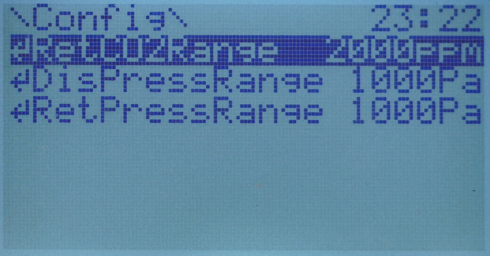
Points in the Config folder
RetCO2Range: return CO2 sensor range;
DisPressRange: discharge pressure sensor range;
RetPressRange: return pressure sensor range.
Schedule
The last component on the list (which is not a typical folder) is Schedule, which allows the user to program the operation modes in time as needed, individually for each day of the week. The scheduling support is described in the AAC20 LCD User Manual.
Sample schedule screenshots:
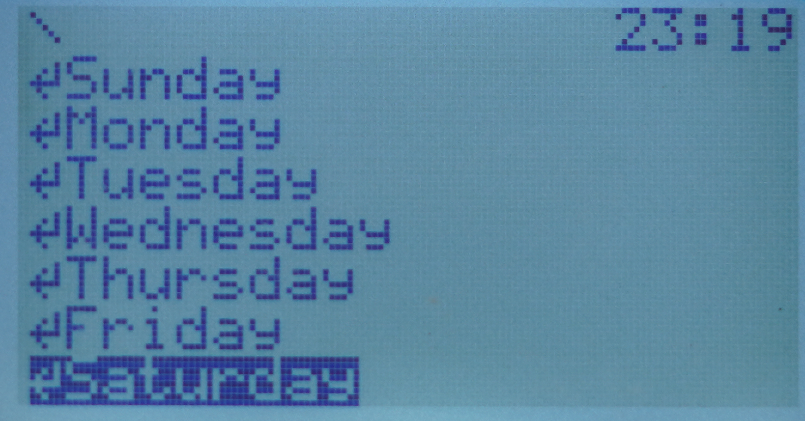
Contents of the Schedule folder
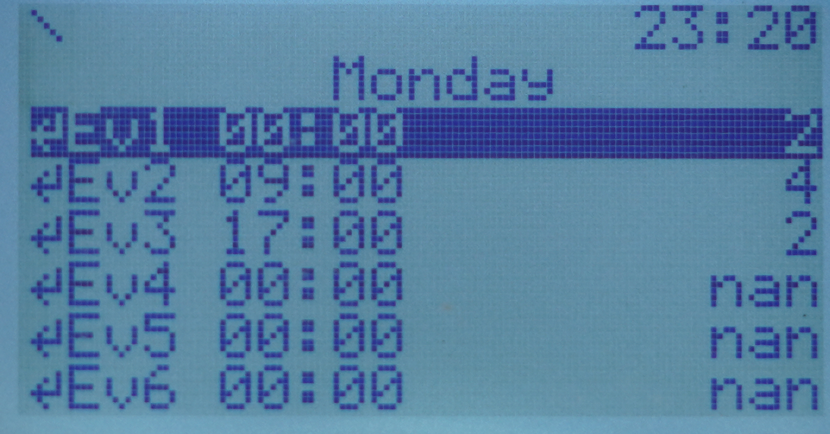
Contents of the Schedule folder
Note: Presently, setting a schedule is recommended in the web server. From LCD, it is now possible to check the schedule’s settings. It is not possible to set the schedule from both locations simultaneously. To set the schedule from the LCD, it is required to switch off the web schedule using the iC Tool (change the Enable slot in the Schedule component under the ModbusTcpSlaveNetwork).
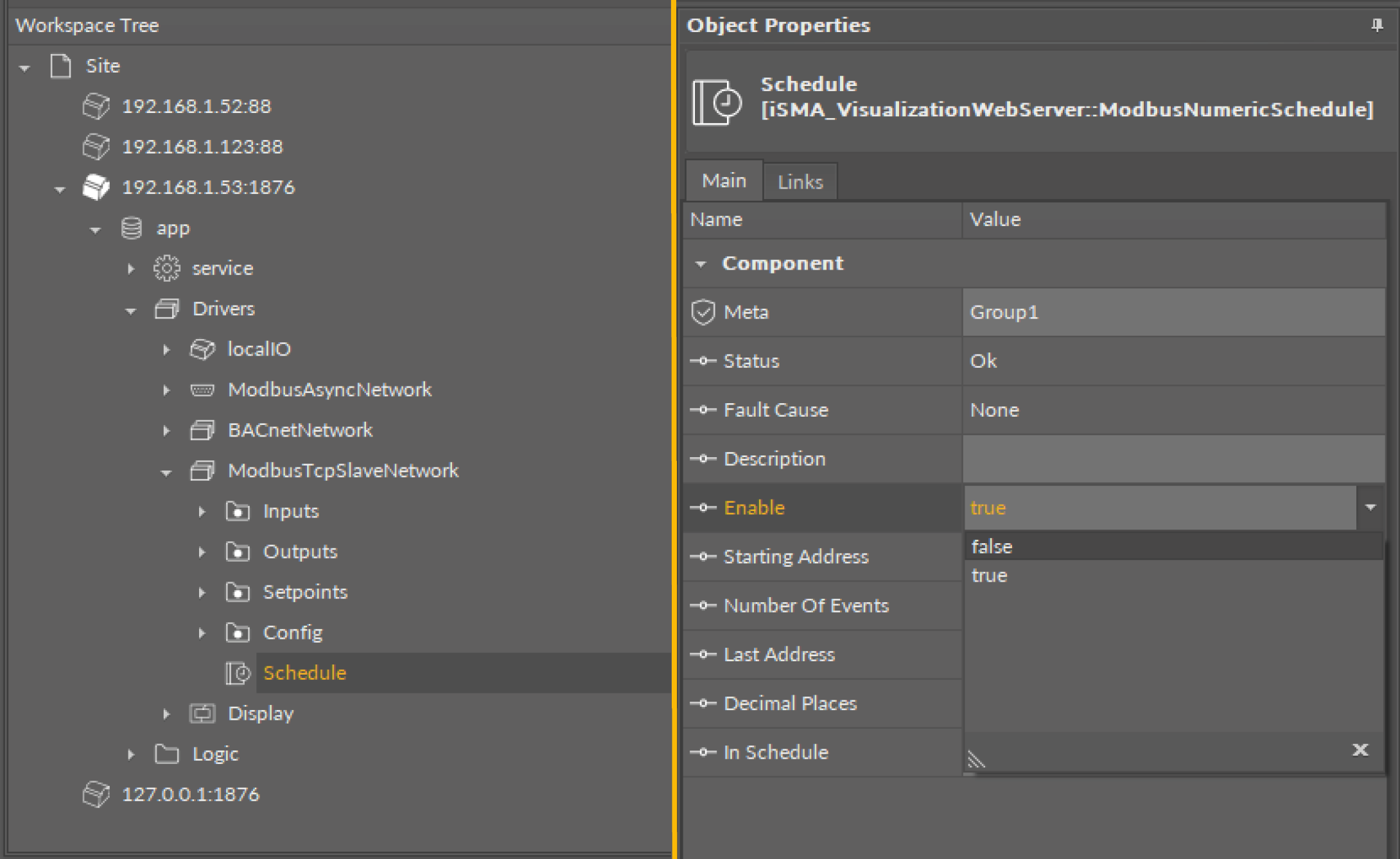
Switching off the web schedule