
PWM
Applicable to library's version 1.0
The PWM component implements a pulse-width modulation (PWM) mechanism. The PWM is based on two slots: Period slot: the time period of the cycle, and Duty Cycle slot: the value of the pulse width, expressed as percentage. The Duty Cycle slot defines the percentage of a time period (value from the Period slot), during which the Out slot is set to true. During the remaining period of time, Out slot will be set to “false”.
For example, according to the values in the figure below:
The Out slot will be set to true for 10 seconds: value from the Duty Cycle slot multiplied by the value from the Period slot (10% * 100s);
After this, the Out slot will be set to false for 90 seconds (90% * 100s);
The state of the Out slot is changed in the above way periodically (in periods defined in the Period slot).
Slots
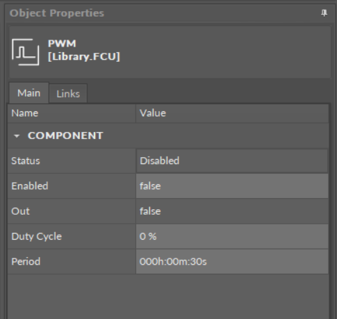
The PWM component has the following slots:
Status: displays the status of the component;
Enabled: enables/disables the component; true: enabled, false: disabled;
Out: the binary output slot with the current state calculated by the component’s algorithm;
Duty Cycle: the numeric input slot corresponding to the pulse width;
Period: the numeric input slot with the period of modulation.