Applicable to OS V1.7
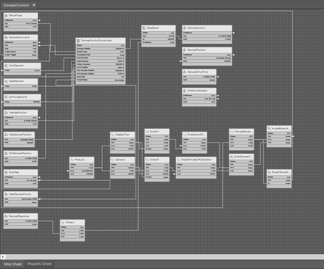
The DamperControl component allows to control of the floating motor of the damper actuator. It allows to set the damper operating mode and it returns the calculated value of the damper opening based on connected PID loops. It also returns the airflow demand for heating or cooling based on the set device type (VAV or VVT).
The DamperControl component has the following slots:
-
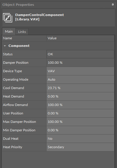
Status: informs about the status of the component; if the Operating Mode slot or one of the demand input slots has a null value then the status is fault, otherwise it is OK;
-
Available statues: OK, Fault, Disabled, Unlicensed, Down, Error;
-
-
Damper Position: shows a calculated damper position according to the damper operating mode;
Note
The damper position is calculated according to the operation mode specifications and taking into account the Max Damper Position and Min Damper Position settings. If the slots are set to values different than 100% and 0%, for example, to 90% and 10%, it means than 10-90% becomes a new full range for the damper operation. It can be used, for example, to fit the damper operation range to the size of the VAV.
-
Device Type: allows to select a preferred device type - VAV for pressure-independent (false) and VVT for pressure-dependent (true);
-
Operating Mode: shows the operating mode from the BMS or panel (from Modbus/BACnet network point) and allows to initiate a damper balancing procedure;
-
Available settings:
-
Auto: the damper is controlled according to the airflow control loop output (for VAV device type) or temperature control loops (for VVT device type),
-
Full Open: the damper control is forced to 100% open position,
-
Full Close: the damper control is forced to 0% open position (closed), even when the MinDamperPosition value is higher than 0%,
-
User Position: the damper control is forced to the user set position (the UserSetPosition variable),
-
Min Flow: the damper control is forced to fit the set minimum airflow for cooling in the occupied state,
-
Max Flow: the damper control is forced to fit the set maximum airflow for cooling in the occupied state,
-
User Flow: the damper control is forced to fit the set user airflow,
-
Calibrate: forces the damper calibration (the damper goes to 0%, then to 100%, and goes back to the control loop output);
-
-
-
Cool Demand: receives the value from the connected cooling PID loop, which determines the damper control for cooling;
-
Heat Demand: receives the value from the connected heating PID loop, which determines the damper control for heating;
Note
The control loops for cooling and heating are mutually exclusive, i.e., only one of them regulates the demand, while the other is disabled.
-
Airflow Demand: receives the value from the connected airflow PID loop, which determines the damper control for a specific airflow demand;
-
User Position: allows to define a damper opening for testing;
-
Max Damper Position: allows to set the maximum damper opening - high limit for the range of the damper operation;
-
Min Damper Position: allows to set the minimum damper opening - low limit for the range of the damper operation;
-
Dual Heat: allows to enable or disable the DualHeat function, which determines of the damper is used as a heating source in systems with a reheater/perimeter);
-
Heat Priority: allows to select a priority order for the primary of heating stage for damper as a heating source.
DualHeat
The DualHeat function allows to select one or two stages of heating (two stages of heating meaning heating with a reheater and, optionally, perimeter and a damper). The DualHeat function is activated according to the setting of the HeatDamperPriority Data Point (linked to the Heat Priority slot in the DamperControlComponent):
-
primary (false): damper in the range of 0-50% (directly from the space temperature heating loop) and heater(s) in the range of 50-100% (indirectly from the discharge temperature heating loop and directly from the space temperature heating loop),
-
secondary (true): heater(s) in the range of 0-50% (indirectly from the discharge temperature heating loop and directly from the space temperature heating loop) and damper in the range of 50-100% (directly from the space temperature heating loop).
Heater(s) in the primary stage can be reheater and/or perimeter. If available in the system and properly configured, they can be arranged in order according to the HeaterPriority variable (ReheaterControl folder):
-
reheater/perimeter
-
perimeter/reheater
-
simultaneous.
If there is no reheater and/or perimeter in the system, the DualHeat function cannot be activated and the damper is the only heating source. If the reheater is available in the system, it can be configured as the primary stage heater and the DualHeat function can be activated. However, if the system is equipped with the reheater and parallel fan, the reheater will always be the secondary:
-
parallel fan/reheater.
More
More on damper control as used in the VAV application: Damper Control