Applicable to OS V1.7
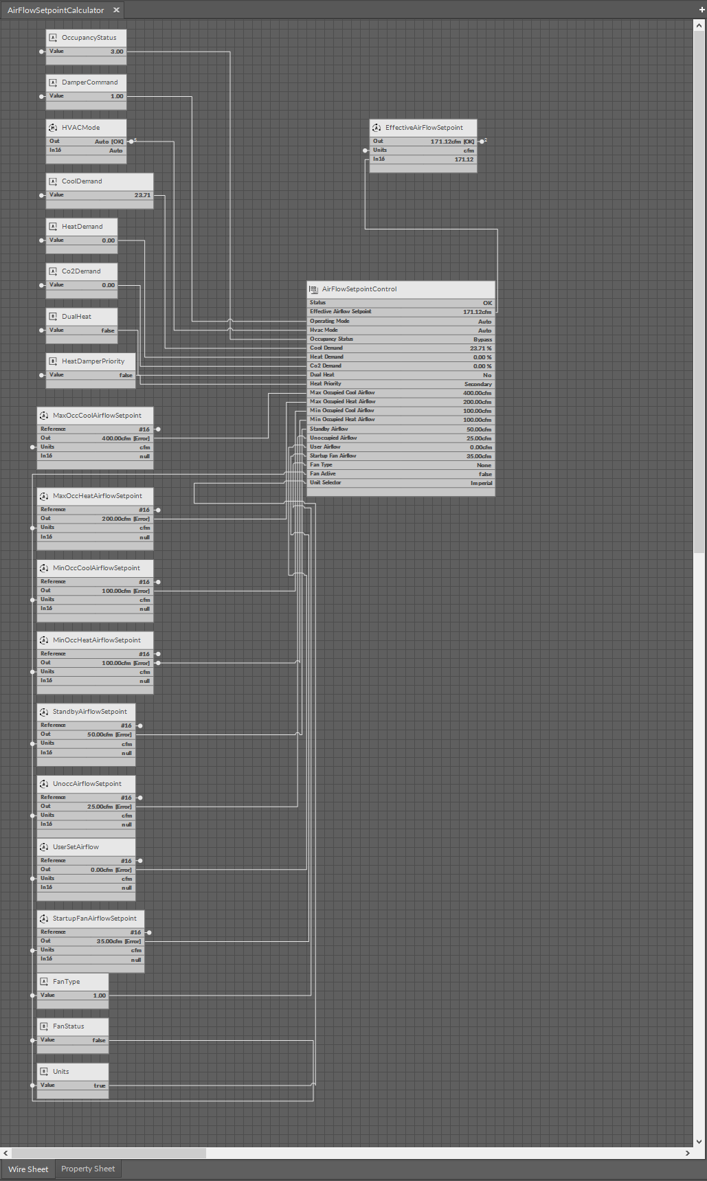
The AirFlowSetpointControl component determines the effective setpoint for regulating the airflow using the damper, based on the output from the temperature control loop for cooling or heating, the setpoints for the minimum and maximum airflow for cooling and heating, the current occupancy status, operating mode (normal, balancing), and HVAC mode.
The AirFlowSetpointControl component has the following slots:
-
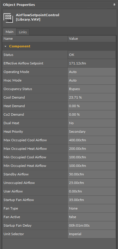
Status: informs about the status of the component; if the Operating Mode/OccupancyStatus/HVAC Mode slot or one of the demand input slots has a null value then the status is fault, otherwise it is OK;
-
Available statues: OK, Fault, Disabled, Unlicensed, Down, Error;
-
-
Effective Airflow Setpoint: returns an airflow setpoint calculated based on the output of the temperature control loop (heating or cooling) and taking into account the setpoint limit values for heating or cooling (Max Occupied Cool Airflow, Max Occupied Heat Airflow, Min Occupied Cool Airflow, Min Occupied Heat Airflow), occupancy mode and occupancy setpoints (UnoccAirflowSetpoint, StandbyAirflowSetpoint);
-
Operating Mode: shows the operating mode from the BMS or panel (from Modbus/BACnet network point) and allows to initiate an airflow setpoint balancing procedure;
-
Available settings: Auto, MaxFlow, MinFlow, UserFlow;
-
-
HVAC Mode: receives the HVAC mode setting, which determines the ariflow setting dependencies and impacts functioning of the fan and heaters (if available on the system);
-
Available settings: Auto, Heat, MorningWarmUp, Cool, NightPurge, PreCool, Off, Fire;
-
HVAC modes
-
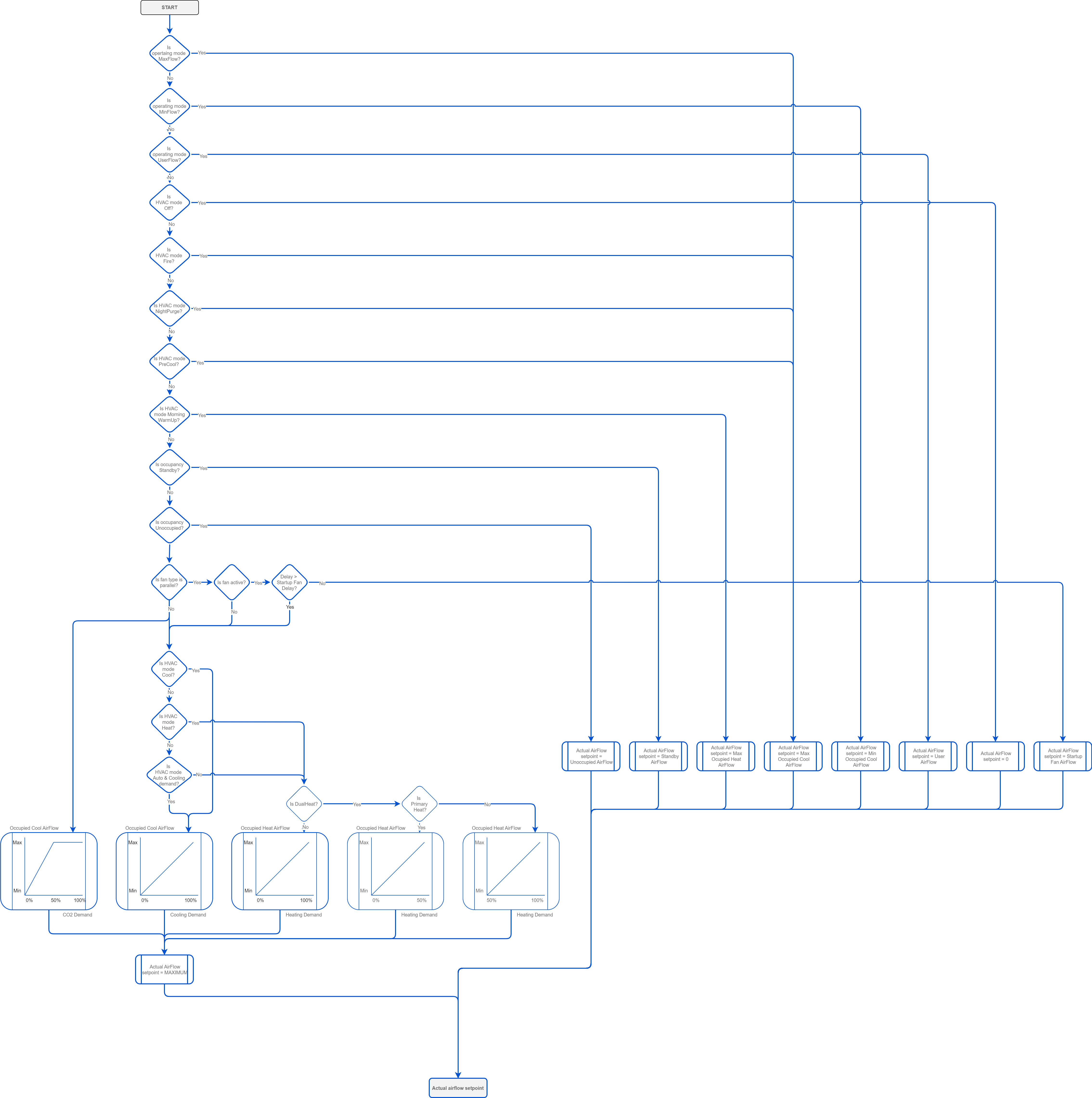
Auto: in the Auto HVAC mode and the operating mode also set to auto, the airflow setpoint is determined by the occupancy status:
-
occupied and bypass:
-
heating: MaxOccHeatAirFlowSetpoint and MinOccHeatAirFlowSetpoint,
-
cooling: MaxOccCoolAirFlowSetpoint and MinOccCoolAirFlowSetpoint;
-
-
standby (StandbyAirFlowSetpoint) and unoccupied (UnoccAirFlowSetpoint): the setpoint is the same for heating and cooling.
-
By default, the maximum airflow setpoint for heating is set as half of the value of the airflow setpoint for cooling.
-
Heat: the airflow setpoint is set depending on the occupancy status:
-
occupied and bypass: between the MaxOccHeatAirFlowSetpoint and MinOccHeatAirFlowSetpoint values - it is a function of the linear heating demand resulting from the heating control loop;
-
unoccupied (UnoccAirFlowSetpoint) and standby (StandbyAirFlowSetpoint), the airflow setpoint is identical to the Auto mode.
-
-
Cool: the airflow setpoint is set depending on the occupancy status:
-
occupied and bypass: between the MaxOccCoolAirFlowSetpoint and MinOccCoolAirFlowSetpoint values - it is a function of the linear cooling demand resulting from the cooling control loop;
-
unoccupied (UnoccAirFlowSetpoint) and standby (StandbyAirFlowSetpoint), the airflow setpoint is identical to the Auto mode;
-
-
MorningWarmUp: the airflow setpoint is set to the MaxOccHeatAirFlowSetpoint, regardless the occupancy status;
-
PreCool: the airflow setpoint is set to the MaxOccCoolAirFlowSetpoint, regardless the occupancy status;
-
NightPurge: the airflow setpoint is set to the MaxOccCoolAirFlowSetpoint, regardless the occupancy status;
-
Fire: the airflow setpoint is set to the MaxOccCoolAirFlowSetpoint, regardless the occupancy status;
-
Off: the airflow setpoint is set to 0, regardless of the occupancy status.
-
Occupancy Status: shows the value coming from the OccupancyCalculator component which is an occupancy status resulting from the values of window contact, present motion, network occupancy, schedule occupancy, airflow detection, and panel button override;
-
Available settings: Occupied, Unoccupied; Standby, Bypass;
-
-
Cool Demand: shows the value from the cooling PID loop;
-
Heat Demand: shows the value from the heating PID loop;
-
Co2 Demand: shows the value from the CO2 PID loop;
-
Dual Heat: provides the component with the DualHeat function status to adjust the effective airflow setpoint calculations in the occupied mode;
-
Available settings:
-
Yes (the DualHeat function active):
-
primary stage (from HeatPriority):
-
for heating demand in the range of 0-50%, scales the effective airflow setpoint between the MinHeatOccAirflowSetpoint and MaxHeatOccAirflowSetpoint values;
-
for heating demand over 50%, effective airflow setpoint equals the MaxHeatOccAirflowSetpoint;
-
-
secondary stage (from HeatPriority):
-
for heating demand in the range of 0-50%, effective airflow setpoint equals the MinHeatOccAirflowSetpoint;
-
for heating demand over 50%, scales the effective airflow setpoint between the MinHeatOccAirflowSetpoint and MaxHeatOccAirflowSetpoint values;
-
-
-
No (the DualHeat function not active);
-
-
-
Heat Priority: provides the component with the heating stages priority to adjust the effective airflow setpoint calculations in the occupied mode as described above;
-
Available settings: primary (true), secondary (false);
-
DualHeat
The DualHeat function allows to select one or two stages of heating (two stages of heating meaning heating with a reheater and, optionally, perimeter and a damper). The DualHeat function is activated according to the setting of the HeatDamperPriority Data Point (linked to the Heat Priority slot in the DamperControlComponent):
-
primary (false): damper in the range of 0-50% (directly from the space temperature heating loop) and heater(s) in the range of 50-100% (indirectly from the discharge temperature heating loop and directly from the space temperature heating loop),
-
secondary (true): heater(s) in the range of 0-50% (indirectly from the discharge temperature heating loop and directly from the space temperature heating loop) and damper in the range of 50-100% (directly from the space temperature heating loop).
Heater(s) in the primary stage can be reheater and/or perimeter. If available in the system and properly configured, they can be arranged in order according to the HeaterPriority variable (ReheaterControl folder):
-
reheater/perimeter
-
perimeter/reheater
-
simultaneous.
If there is no reheater and/or perimeter in the system, the DualHeat function cannot be activated and the damper is the only heating source. If the reheater is available in the system, it can be configured as the primary stage heater and the DualHeat function can be activated. However, if the system is equipped with the reheater and parallel fan, the reheater will always be the secondary:
-
parallel fan/reheater.
-
Max Occupied Cool Airflow: receives a maximum airflow setpoint in the occupied state, set during the balancing process;;
-
Max Occupied Heat Airflow: receives a maximum airflow setpoint in the occupied state, set during the balancing process;;
-
Min Occupied Cool Airflow: receives a maximum airflow setpoint in the occupied state, set during the balancing process;;
-
Min Occupied Heat Airflow: receives a maximum airflow setpoint in the occupied state, set during the balancing process;;
-
Standby Airflow: receives an airflow setpoint set from the BMS system and, optionally, from the local room panel, when the room is temporarily unoccupied;
-
Unoccupied Airflow: receives an airflow setpoint set from the BMS system and, optionally, from the local room panel, when the room is unoccupied;
-
User Airflow: receives an airflow setpoint set for tests in the balancing process;
-
Startup Fan Airflow: receives a value of minimum airflow starting the parallel fan; after the Startup Fan Delay time has elapsed, normal control starts (airflow control according to the calculated setpoint);
-
Fan Type: allows to select a preferred fan type as series or parallel; version without fan is None;
-
Fan Active: the rising state on this slot causes the Startup Fan Airflow setpoint to be used for the time specified in the Startup Fan Delay slot; after the time has elapsed, normal control starts;
-
Startup Fan Delay: allows to set a startup time with a minimum airflow specified in the Startup Fan Airflow slot;
-
Unit Selector: allows to set the unit type.