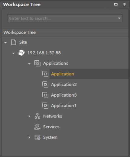
The basic idea of the Applications container is to group the components meant to build applications.
Applications built with the nano EDGE ENGINE driven devices have unique characteristics:
- cycle-driven (the components included in the application are executed in repeated periods of time lasting as long as a cycle is set–the duration of the application cycle can be set by the user, and may be even as short as 15 ms)
- multithreaded (the user can have more than one application, all working simultaneously)
- real-time operation (the nano EDGE ENGINE is so fast that the applications are executed effectively real-time)
- Data Points (with automatic BACnet and Modbus exposition) (basic components for applications, including priorities and allowing Reference linking)
- Reference links (unique linking method for Data Points and network points that allows to transfer the value along with the component's status)
Applications
In order to build universal applications, the place of reference is the Applications container. The first step is to place the Application component in the Applications container (or as many of them as necessary–with the nano EDGE ENGINE it is possible to create more than one user application on the device, and all of the applications are cycle-driven and can work simultaneously).

Multiple applications
Once the Application component is added to the Applications container, it is ready to have the Data Points added, and the user application with complementary components can now be created. The components needed for this purpose are grouped in the Applications libraries.
The distinctive thing about the Data Points used in the applications is that they are BACnet and Modbus native–each Data Point contains built-in BACnet and Modbus extensions, which allow to automatically expose it as a BACnet object to the BACnet network and Modbus point to the Modbus network.
Using Equipment Folders
Good Practice Tip
In future developments, the RAC18-IP controller will have a Haystack functionality implemented in its firmware, which calls for some good practice mechanisms that can be introduced now, with the current functionalities.
The Haystack functionality will offer multiple advantages of using tags–it will help identify parts of equipment controlled by the application and used Data Points, filter data by equipment, sensor, or value, any many more.
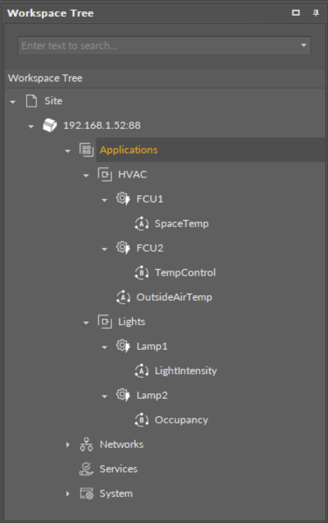
In order to facilitate a future use of the full Haystack functionality, the Equipment component has been included in the Core library. It is therefore recommended to use the following structure when creating applications:
-
Applications container
-
Application component
-
Equipment component
-
Data Point(s)
-
other components
-
-
Equipment component
-
Data Point(s)
-
other components
-
-
-
Such structure will be fully recognized in the Haystack functionality and will require minimum effort to use its full potential once updated.

Difference Between Equipment and Folder Components
The Equipment component with Haystack functionality will allow to identify the types and other characteristics of controlled devices by tags, which will be a main difference between the Equipment and Folder components–the Folder component is merely an organizing component; in the future, it will not carry any Haystack tags functionalities. It is therefore very important to use the Equipment components in the applications structure.
Also refer to: Equipment Manager
Data Points
Data Points are universal components that represent a value in the application logic; they may serve as setpoints, sensors values, non-volatile variables, or any other data values. Data Points represent a layer of the application logic that is presented to an end user—this is where the end user is able to adjust desired setpoints (e.g., for air conditioning) or evoke other actions outlined in the application logic. Data Points also read values calculated in applications and control local or remote outputs.
Data Points in the application logic may work as regular writable variables with priorities, or—with Reference linking—they may be connected with network points, such as local I/O components.
Data Points are universal components that facilitate building application logics. They are adaptable by extensions, which expand their functionality by enabling them to be exposed to communication protocols. Among the fundamental extensions for Data Points are AnalogPriorities, BinaryPriorities, and MultistatePriorities—they add 16 priority input slots to Data Points, which allows to build logics based on using value significance priorities—a value given in the highest priority slot dismisses all values of lower priorities, which enables, for example, making sure that no emergency is omitted due to values of lower significance. Slots, which are not linked and have a value entered, save the value on a given priority.
The available Data Points:
-
AnalogDataPoint with native BACnetAnalogPoint and ModbusAnalogPoint extensions;
-
BinaryDataPoint with native BACnetBinaryPoint and ModbusBinaryPoint extensions;
-
MultistateDataPoint with native BACnetMultistatePoint and ModbusMultistatePoint extensions.
In order to operate properly, Data Points must be placed in one of Application components in the Applications container. Only from this position, they may work properly included in the application logic.
Data Points and Network Points
Simply put, in the nano EDGE ENGINE, Data Points are value-carriers, and network points are communication-carriers. Data Points are always located in the Applications container (in individual Application components), and network points are always located in the Networks container (in the LocalIO component or BACnet/Modbus devices). The below table lists nano EDGE ENGINE component referred to as Data Point–and network point–class components:
|
Data Point class components |
Network point class components |
|---|---|
|
AnalogDataPoint BinaryDataPoint MultistateDataPoint |
UniversalInput (LocalIO) DigitalInput (LocalIO) DigitalInputCounter (LocalIO) AnalogOutput (LocalIO) DigitalOutput (LocalIO) TriacOutput (LocalIO) DipSwitch (LocalIO) AnalogPoint (BACnet/Modbus device) BinaryPoint (BACnet/Modbus device) MultistatePoint (BACnet/Modbus device) StringPoint (Modbus device) AnalogCustomPoint (BACnet device) BinaryCustomPoint (BACnet device) StringCustomPoint (BACnet device) |
Data Point– and network point– class components
Remember - Great Licensing Scheme
The Applications container includes the only elements subject to license in the nano EDGE ENGINE devices.
The license for the new generation of iSMA CONTROLLI controllers driven by the nano EDGE ENGINE is constructed against the number of Data Points: each device based on the nano EDGE ENGINE is granted a specified number of license points (Data Points in this case), which can be used within applications. Therefore, the licensing system is only of quantitative, not functional, character–only the real number of Data Points in applications is taken into account, regardless of how many communication protocols are used to expose them, or how many network points are controlled. With the nano EDGE ENGINE-generation devices it is possible to create as big an application (or applications) as the number of licensed Data Points. No elements in the Networks, Services, or System containers are subject to license limitations, other than Data Points in the Applications container.
Note: In order to check the number of license points, please refer to the License in the device.
