Applicable to OS V1.4
The MultistateDataPoint component is a component that represents an analog integer positive value in the application; it reads values calculated in applications and controls local or remote analog outputs. The MultistateDataPoint allows to create standard links to all inputs and outputs.
In order to operate properly the component must be placed in the Application component in the Applications container.
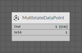
The MultistateDataPoint on the Wire Sheet view
The MultistateDataPoint can operate in two configurations. First, it is a basic configuration with one writable input slot (In16), one output slot (Out), and other basic slots: Mode, Units, Status, Enabled, Description. In the basic configuration, the MultistateDataPoint has native BACnetMultistatePoint and ModbusMultistatePoint extensions.
The MultistateDataPoint slots
The MultistateDataPoint has the following basic slots:
-
Status: indicates the current status of the component. If the component works properly, its status is OK; however, it changes accordingly when values in other slots are adjusted.
-
Available information: Disabled, Unlicensed, Error, Overriden, OK;
-
-
Reference: slot for future use.
-
Description: an additional detailed information about a component that may be freely described by the user; the description may contain individual coding defined in the user's system documentation or any other information the user finds applicable.
-
Enabled: change of the slot's value enables or disables the component–if the component becomes disabled, it stops reading values from or transferring values to the linked network points. By default, the component is enabled.
-
Available settings: true (enabled), false (disabled).
-
-
Mode: allows to set a mode of the component, which defines the type of data exposed on specific protocol’s server if it is read-only or writable;
-
Available settings: Value, Input, Output;
-
-
Out: shows a value transferred from the In16 slot in the basic configuration, or from the first non-null input with highest priority in the extended mode; in case there are values on different priorities, only the value from the highest priority slot is transferred to the Out slot, the rest is dismissed.
Note: In the Wire Sheet the Out slot is visible as combined slots Out, Units, Priority (which is a source of the Out slot value; shown in the extended mode), and Status.
Note: If labels are set for values in the MultistateDataPoint, the Out slot will display the label. If the Out slot has an outgoing link to another component, the only the numeric value will be transferred.
-
In16: the basic input slot; receives analog values; the In16 value may be set by a Set action;
The MultistateDataPoint has the following basic actions:
-
Set: allows entering an analog value to set the In16 slot;
-
SetId: sets a BACnet object Id of the MultistateDataPoint (exposed in the BACnetMultistatePoint extension);
-
SetAddress: sets a Modbus address of the MultistateDataPoint (exposed in the ModbusMultistatePoint extension).
The extended configuration of the MultistateDataPoint is switched on by adding the AnalogPriorites extension to the MultistateDataPoint component. The extension adds 16 writable input slots to the Data Point. It is added by right-clicking on the MultistateDataPoint component (either in the Wire Sheet or Property Sheet view).
Labels
In MultistateDataPoints it is possible to set labels for different values. Labels are individual representations for default values in the Data Point, for example, it is possible to set individual value for any integer value that will be displayed instead. Labels applied in a component are visible on every component's view (Wire Sheet, Property Sheet, Object Properties, etc.).
To edit labels for the MultistateDataPoint, go to the component's context menu and select the Edit Labels option. The dialog window appears to edit labels for each value:
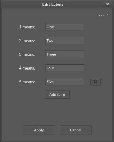
Edit labels dialog window
In the top right corner of the dialog window, the dots/arrow button displays preset lists of labels for specific purposes:
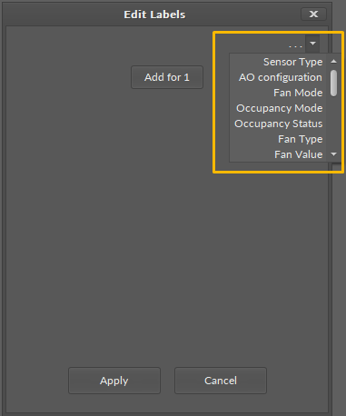
Preset lists of lables
Note: Please note that labels are only representations of the integer values of the MultistateDataPoint, they are not string values. When transferred by a link to another component, the source integer value is sent without an assigned label.
Extensions
Data Points can have their functionality modified by extensions. The MultistateDataPoint is originally equipped with the BACnetMultistatePoint and ModbusMultistatePoint extensions (these cannot be added or removed), but other extensions, which offer different functionalities, can be added or removed as necessary. Extensions are added by right-clicking the MultistateDataPoint, either in the Wire Sheet or Property Sheet view, Application Manager, or in the Workspace Tree.
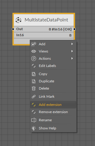
Adding extension in the Wire Sheet view
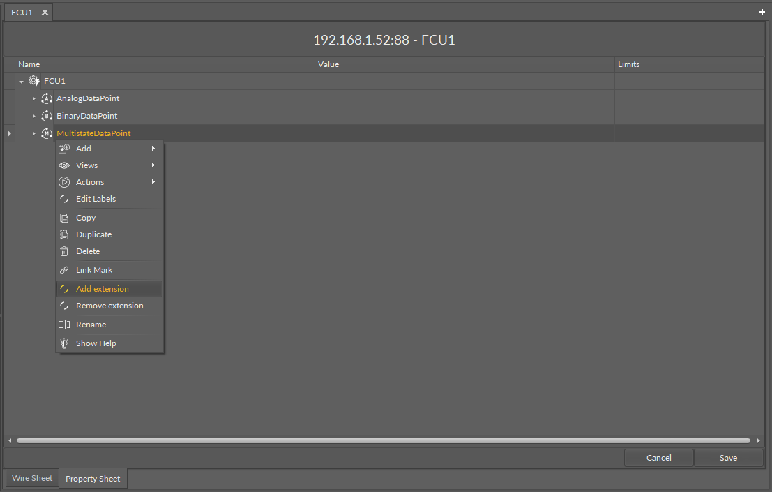
Adding extension in the Property Sheet view
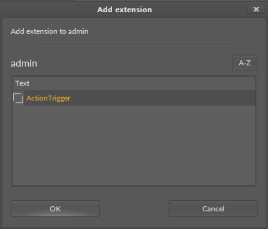
From the context menu, select the Add Extension option. The pop-up window appears allowing to choose an extension to add.
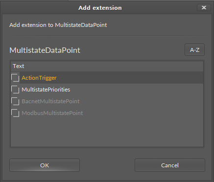
Adding extension
BACnetMultistatePoint
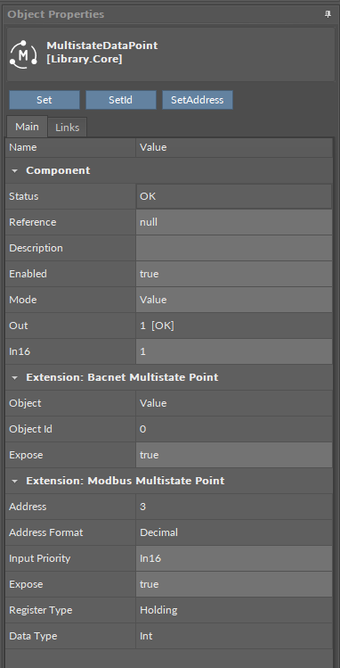
The BACnetMultistatePoint extension expands the MultistateDataPoint's functionality giving it an option to expose it to the BACnet IP network as an Analog Value object, and, otherwise, it allows to manually hide it from the network yet preserving its function in the application. It also transfers information to the BACnet IP network about the MultistateDataPoint's status. The extension is native (cannot be removed), and is visible along with the regular slots and actions of the MultistateDataPoint as a separate, integral part in the Object Properties view.
The extension has the following slots:
-
Object: a read-only slot showing a type of BACnet object attributed to the extension;
-
ObjectID: a BACnet object ID, which is automatically numbered from 0 up;
-
Expose: enables the Data Point to be recognized within the BACnet IP network;
-
Available settings: true (exposed), false (hidden).
-
ModbusMultistatePoint
The ModbusMultistatePoint extension expands the MultistateDataPoint's functionality giving it an option to expose it to the Modbus TCP/IP network as a Modbus point, and, otherwise, it allows to manually hide it from the network yet preserving its function in the application. It also transfers information to the Modbus TCP/IP network about the MultistateDataPoint's status. The extension is native (cannot be removed), and is visible along with the regular slots and actions of the MultistateDataPoint as a separate, integral part in the Object Properties view.
The extension has the following slots:
-
Address: a read-only slot showing a Modbus register, which the Data Point is exposed on;
-
Address Format: a read-only slot showing a register address format;
-
Available information: decimal, Modbus, HEX;
-
-
Input Priority:
allows to select the input number in the Data Point, which the value from the register is synchronized on;
-
Expose: enables the Data Point to be recognized within the Modbus TCP/IP network;
-
Available settings: true (exposed), false (hidden);
-
-
Register: a read-only slot showing the type of the register used;
-
Available information: holding register;
-
-
Data Type: allows to select a value data type;
-
Available settings: integer (default), signed integer, long, signed long, float, double.
-
Apart from the BACnetMultistatePoint and ModbusMultistatePoint, it is possible to add the following extensions to the MultistateDataPoint:
MultistatePriorities
The MultistatePriorities extension adds fifteen writable input slots and the default (lowest) priority slot to the MultistateDataPoint. The extension includes the Priority slot indicating, which slot is transferring value to the Out slot. The AnalogPriorites extension adds In1–In15 slots and the Default slot, which is the lowest, 17th priority. The extension also introduces new actions to the Data Point: EmergencyOverride, EmergencyAuto, Override, and OverrideAuto.
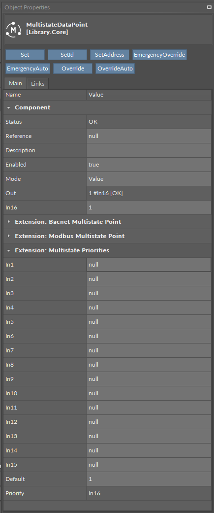
The MultistatePriorites extension
The MultistateDataPoint has the following slots available in the MultistatePriorities extension:
-
In1-In15: input slots providing values to the Out slot (from 1 to 16, the highest priority is In1); only the highest priority value is provided to the Out slot, the rest is dismissed. All input slots are linkable. In the extended mode, the In1 and In8 slots have actions available for overriding their values.
Note: By default, only the In16 is displayed in the Wire Sheet. In case any other input slot receives a value via link, is it displayed in the Wire Sheet along with the In16. Only the null input, which is a lack of value, allows the higher priority input to be dismissed–zero (0) is still a value that will be provided to the Out slot.
-
Default: the 17th, lowest priority input slot; allows to introduce a default value to the Data Point in case there are no links providing values from other components.
Note: According to BACnet requirements, the Default slot value can never be null; if no other value is set on the slot, it is zero (0).
-
Priority: shows, which slot is currently providing the value to the Out slot.
The MultistateDataPoint has the following actions available in the MultistatePriorities extension:
-
EmergencyOverride: enables entering an analog value to the In1 slot;
-
EmergencyAuto: sets the null value to the In1 slot (cancels the EmergencyOverride action);
-
Override: enables entering an analog value to the In8 slot;
-
OverrideAuto: sets the null value to the In8 slot (cancels the Override action).
Note: If the link is connected to the slot that may be affected by an action, the value coming from the link connection has priority over the manually evoked action.
ActionTrigger
The ActionTrigger extension is designed to invoke any action that is available for the component. The extension triggers an action selected in the Action Name on the rising edge of the Action Trigger slot. If the action has parameters to set, the parameter is taken from a relevant slot automatically added to the extension (Analog Value/Binary Value/String Value).
It is possible to add more than one ActionTrigger extension to the component (for example, one for each action in the component).
The extension is added from the context menu of the component.
The ActionTrigger extension has the following slots:
-
Action Name: allows to select an action to invoke;
-
Action Trigger: triggers an action selected in the Action Name slot;
-
Action Analog Value/Action Binary Value/Action String Value: a slot added automatically to the extension if an action selected in the Action Name slot has any specific parameters to set (depending on the type of action and its parameters, the relevant type of value is matched).
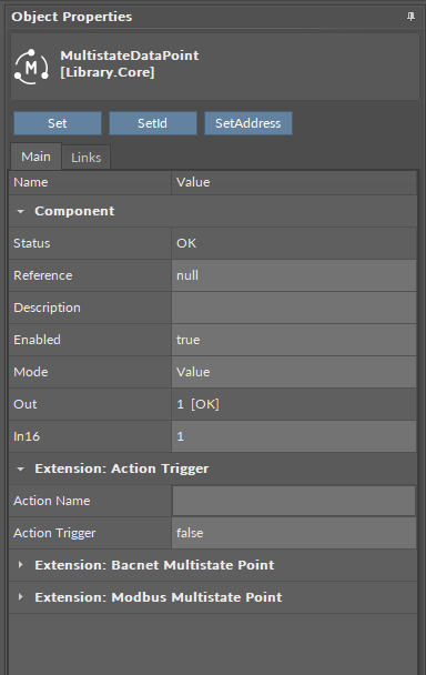
The ActionTrigger extension in the MultistateDataPoint