General Functionalities
This chapter describes the user interface of the RS485 Configurator, which is the most advanced of the 2 available tools. In the user interface of the USB configuration tool, the Info tab does not include the functionality to show the charts, but is possible to use the USB Configurator in the offline mode (simulator), and there is also the Upgrade FW tab.
Opening the application, the following user interface will be displayed:
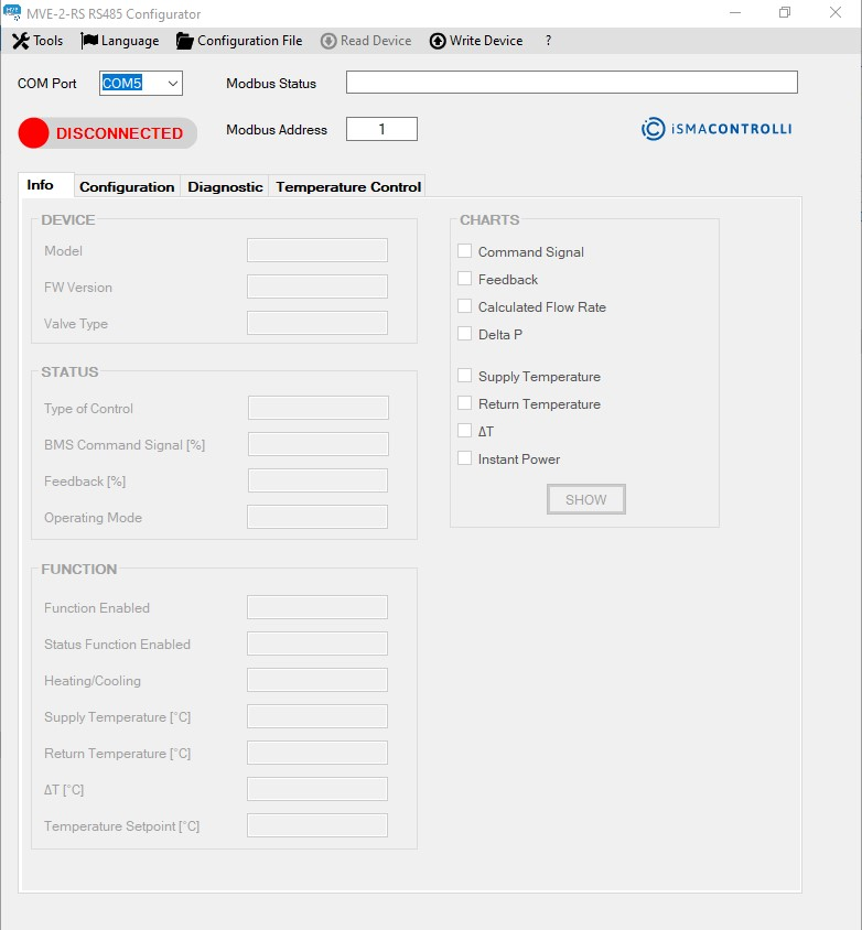
User interface at the startup
To enable the tabs, it is necessary to select the COM connected to the USB-RS485 converter and click the toggle button with the DISCONNECTED label. If the connection is successful, all tabs will be enabled. To list all COM ports available, click the COM port label.
The user interface allows the following functionalities:
-
reading the main characteristics of the actuator and show real-time graphics (Info tab);
-
configuring the actuator (Configuration tab);
-
checking the actuator's status and its anomalies (Diagnostic tab);
-
enabling the temperature loop functions (Temperature Loop tab). The sections inside this tab are enabled based on the Enabled function;
-
setting the Modbus parameters to connect to the actuator with the Modbus master (not available in the USB version);
-
uploading a configuration file or download the set parameters in a configuration file;
-
selecting the language (Italian or English).
When either if the tabs is selected, all parameters shown in the page will be refreshed.
WARNING!
To read a parameter inside the tab, it is necessary to click the corresponding label. If the value to be read is inside a specific section (e.g., supply temperature), clicking the label of this section will invoke reading of all the values on the list.
To write a parameter inside a textbox, it is required to press Enter after a new value is entered or after selecting an item from a dropdown menu.
Dropdown Menu
The main window at the top shows the following dropdown menu:
Dropdown menu
-
Tools: allows to define the Modbus connection options related to the iSMA-B-CVT-RS485 converter. If the user intends to change the Modbus connection options, the parameters have to be changed before clicking the toggle button to connect to the Modbus configuration tool:
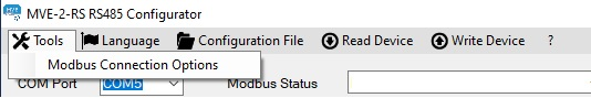
Tools menu
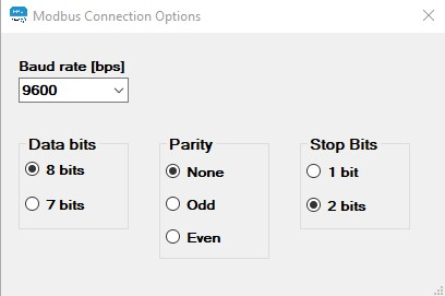
Modbus connection options
-
Language: allows to choose a language: Italian or English.
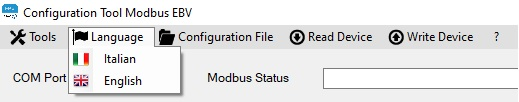
Language menu
-
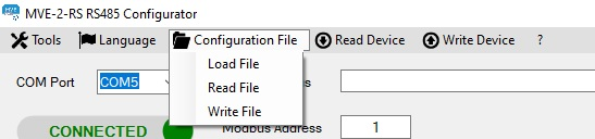
File Configuration: allows to:
-
Load File: load a .csv file with actuator parameters and send them to the actuator;
-
Read File: load a .csv file to show values on the tabs of the configurator without sending them to the actuator;
-
Write File: save a .csv file with the parameters set on the configurator.
-
Note: Only writable parameters will be saved in the .csv file.
File configuration menu
-
Read Device: allows to update the values in all tabs of the configurator;
-
Write Device: allows to write all configuration parameters into the actuator;
-
?: allows to read the software version of the configurator.
Other Functions
The following other items are shown:
-
CONNECT/DISCONNECT toggle button: connects/disconnects the RS485 configurator. In the MVE-2-RS USB Configurator, the toggle button enables/disables the connection with the actuator via USB. In the MVE-2-RS USB Configurator, the offline mode is available. The offline mode allows the user to use the configurator without the need of a real actuator connected to the USB of the PC. Offline mode is not available in the MVE-2-RS RS485 Configurator.
Default settings for the connection are:
-
baud rate: 9600;
-
no parity bit;
-
2 stops bits.
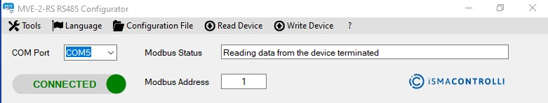
When the application starts, the toggle button is in the DISCONNECTED status; to initiate the communication between the actuator and master device, it is necessary to click the toggle button and the status of the button will change to CONNECTED.
If the connection has been successful, the Modbus Status label will state OK.

Status USB shows the status of the USB communication
To disconnect the Modbus communication between the actuator and master device, click on the toggle button when it is in the CONNECTED status. If the disconnection has been successful, the DISCONNECTED notice will appear in the Modbus Status field.
-
COM PORT (dropdown list): if the serial converter is already connected at startup, only the relative COM port is shown. Otherwise, click the COM PORT label above the dropdown menu; all the COM ports active on the PC will be listed. To select the correct COM port, which the USB-RS485 converter is connected to, follow the procedure in the Modbus Configuration section;
-
Modbus ADDRESS (textbox): shows the Modbus address of the device, which all the operations will be performed on through the configurator. By default, the address is set to 1;
-
Modbus STATUS (textbox): allows to view the status of the Modbus communication showing the outcome of the performed actions. If an action is successful, the OK status is shown.
Modbus Configuration
In the upper area of the main window, there is a dropdown list that displays the COM port currently in use by the PC. To identify the number of the serial port (COM Port), which the USB-RS485 converter is connected to, it is necessary to access the PC Control Panel and select the Device Manager:
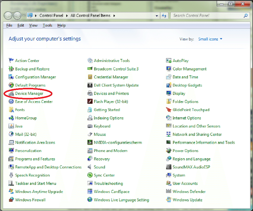
Device Manager in the Windows Control Panel
Select the Ports (COM and LPT) field to check the serial port number, which the serial converter is connected to (COM5 in the example below).
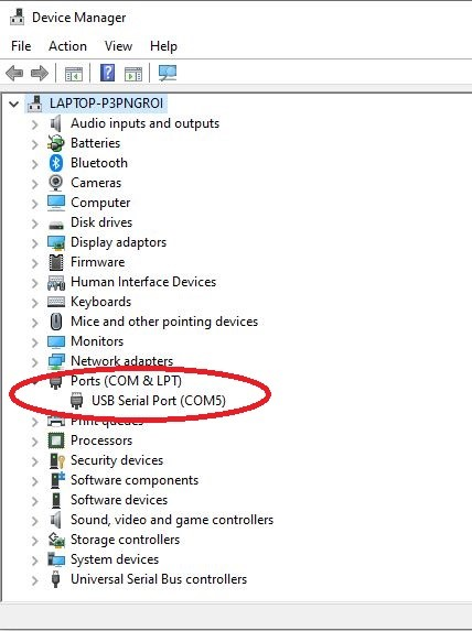
Device Manager Windows
Once the COM port has been selected, click the CONNECTED/DISCONNECTED toggle button, and verify if the Modbus Status is OK.
As indicated in the previous section, the Modbus configuration parameters of the master can be selected through the dropdown menu: Tools → Modbus Connection Options. The changes of the Modbus connection parameters of the master must be done prior to clicking the connect toggle button.
By default, the communication parameters are:
-
baud rate 9600;
-
no parity bit;
-
2 stop bits.
Tabs
Info Tab
In this window, it is possible to read the main information about the actuator:
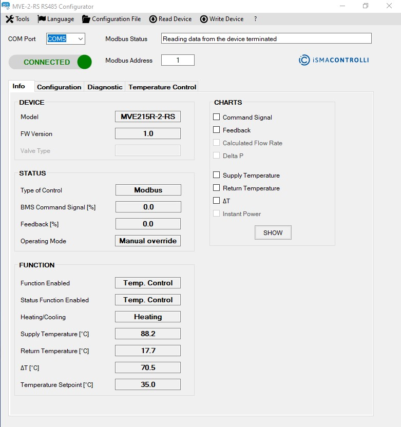
Info tab
-
Model: represents the product part number. The alphanumeric code is composed as follows:
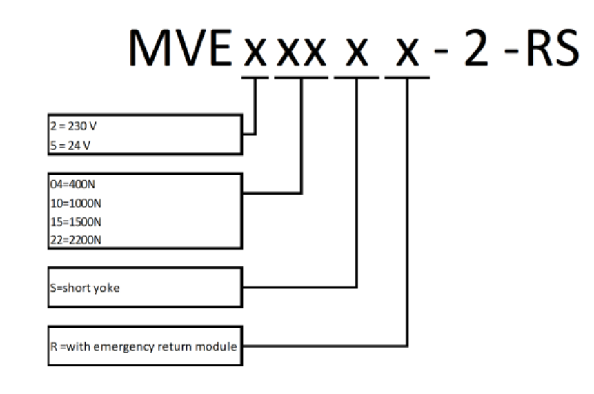
Example code
An example of the code is the following: MVE510S-2-RS, which represents an MVE-2-RS model with 1000 N of force, powered at 24 V AC without emergency return, Modbus communication, and short stroke.
The value cannot be changed in the configurator.
-
FW Version: identifies the current version of the firmware installed on the actuator;
-
Valve Type: not available;
-
Type of Control: shows the command type for the actuator (the default value is 0-10 V, selectable by a DIP switch);
-
BMS Command Signal [%]: shows the current Modbus command signal value (between 0-100%).
Note: It is a read-only value. The BMS command is set in the Configuration tab.
-
Feedback [%]: allows to identify the position of the actuator in the 0-100% range of the stroke;
-
Operating Mode: shows the operating status of the actuator, which can be one of the following:
-
Normal: the actuator is working following the command signal at its input; therefore, it is not in the initial positioning, calibration, emergency return, or manual command inserted phases;
-
Initial positioning: the actuator is moving towards the initial position determined by the DIP 1 or, if the DIP switches are disabled, based on the action type value set in the Configuration tab;
-
Calibration: the actuator is calibrating the stroke;
-
Error: indicates that one or more errors have occurred; the details of the error are visible in the Errors section of the Diagnostics tab;
-
Manual override: shows that the manual command has been enabled; the actuator does not respond to the command signal until the manual override is disengaged and the initial positioning ends;
-
Fail-safe: shows that the actuator is in the emergency return phase due to the lack of power supply. This operative mode is available only for the emergency return models.
-
-
Function Enable: shows which of the following functions is currently enabled:BMS: the actuator is controlled by the input signal (voltage or current control) or by the Modbus command;Temperature Control: the function constantly overrides the control signal to maintain the set ΔT by closing or opening the valve;∆T limitation: the actuator is controlled by the input signal (voltage or current control) or by the Modbus command but, if the ∆T goes below the temperature limitation set (heating or cooling), the actuator overrides the command closing the valve;Temperature Maximum Limitation: the actuator is controlled by the input signal (voltage or current control) or by the Modbus command but, if the temperature exceeds the temperature limitation set (heating or cooling), the actuator:opens the valve in cooling,closes the valve in heating;Temperature Minimum Limitation: the actuator is controlled by the input signal (voltage or current control) or by the Modbus command but, if the temperature goes below the temperature limitation set (heating or cooling), the actuator:closes the valve in cooling,opens the valve in heating;
-
Status Function Enable: shows a currently active function in real time;
-
Heating/Cooling: shows whether the heating or cooling control mode is active;
-
Supply Temperature [°C]: represents the temperature value, in °C, detected by the supply temperature sensor (it is the sensor connected to the T1 input of the terminal block). It is a read-only value.
Note: If a value of 500.0 is displayed, it means that the supply sensor (T1) is disconnected or faulty, and the relative TEMPERATURE SENSORS groupbox is disabled (the groupbox is gray). In case functions, which require that temperature sensors are enabled, this error condition is also highlighted in the Diagnostics tab. In case a temperature sensor anomaly occurs, all the related functionalities are disabled.
-
Return Temperature [°C]: represents the temperature value, in °C, detected by the sensor positioned at the valve outlet port (it is the sensor connected to the T2 input of the terminal block). It is a read-only value.
Note: If a value of 500.0 is displayed, it means that the return sensor (T2) is disconnected or faulty, and the relative TEMPERATURE SENSORS groupbox is disabled (the groupbox is gray). In case of functions which require that the temperature sensors are enabled, this error condition is also highlighted in the Diagnostics tab. In case a temperature sensor anomaly occurs, all the related functionalities are disabled.
-
∆T [°C]: shows a difference between the supply and return temperature value, in °C;
Note: If the temperature sensors have problems or are not connected, no value will be displayed.
-
Setpoint: shows a setpoint configured for the currently enabled function;
-
CHARTS: by checking the items listed in this section, it is possible to view the charts of the desired variables. The graphs are grouped into 2 types: the Control charts (command signal, feedback) and the Temperature charts (supply temperature, return temperature, delta T). clicking the CHARTS button, a window will appear with selected charts. The 2 types of variables are represented on 2 different graphic areas (see the figure below).
WARNING! The CHARTS functionality is NOT available in the MVE-2-RS USB Configurator.
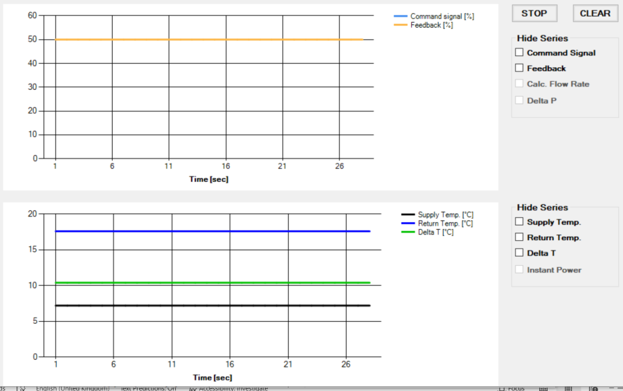
The charts window
The window shows the 2 areas for the 2 types of charts described above. The charts displayed are those selected in the Info tab, and they are updated every second starting from the opening of the window in the specific chart area.
It is possible to stop updating charts and display them by clicking the STOP button, and resume updating by clicking the START button (the same button, therefore, allows to stop or restart the display). When updating is resumed, the first data displayed will be the current one and not the one at the time of the stop (therefore, the data will be lost during the time the chart stops).
It is possible to hide one or more plotted graphs from the display by marking checkboxes in the Hide series section (the series is hidden, but the acquired data continues to be stored anyway).
It is again possible to show the previously hidden graphs by removing the check mark from the specific box; as mentioned, the graphs will show a temporal continuity in the data even if they were hidden.
The RESET button allows to delete the graphs from the display area.
After 90 minutes the charts are no longer updated because the maximum number of data that can be displayed has been reached. A pop-up message warns the user, and asks if the data should be saved to a file (.csv); if the the action is confirmed with the Yes button, a window is opened for saving the file, and, once the name of the file is indicated, the charts in the two areas are deleted. By clicking the No button, the data are not saved to the file, and the charts will be deleted. By clicking, the START button, it is possible to restart the data display from the current instant.
Configuration Tab
In this window, it is possible to set the following actuator's configuration parameters:
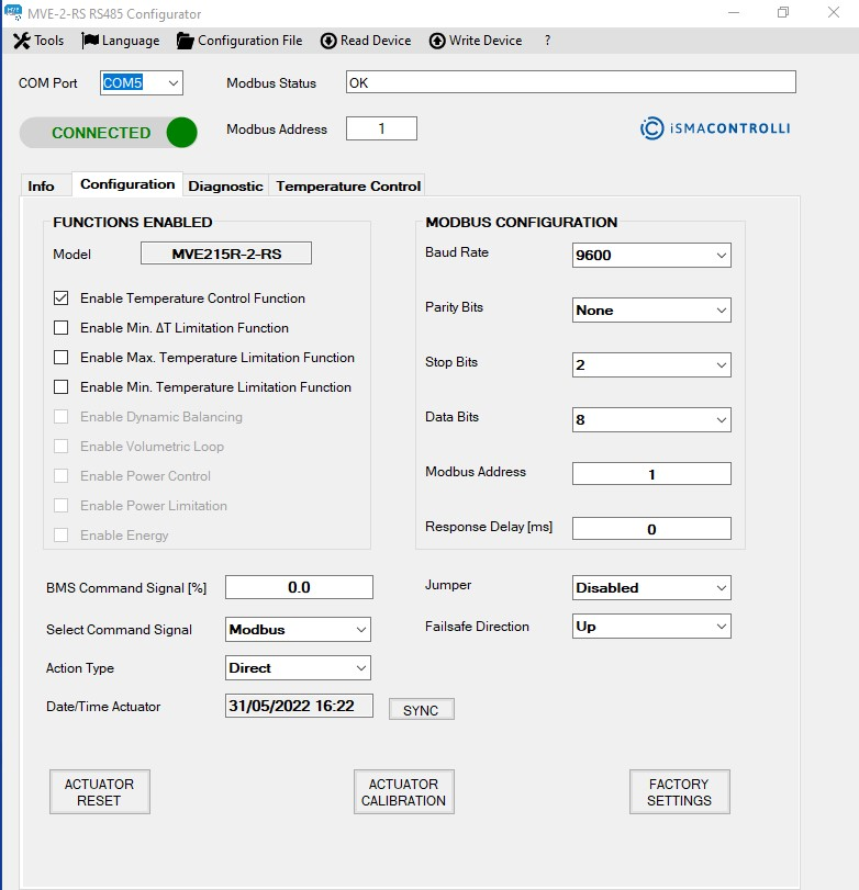
Configuration tab
-
FUNCTIONS ENABLED: shows the available functions for the actuator model;
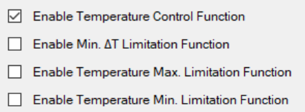
Selection of functions to enable
-
MODBUS CONFIGURATION: allows to set the Modbus configuration parameters of the actuator, in particular:
-
Baud Rate: 9600 or 19200;
-
Parity Bit: sets the parity bit to none, odd, or even;
-
Stop Bits: 1 or 2.
-
Note: The factory settings of the actuator are: baud rate 9600, no parity bit, and 2 stop bits.
-
Modbus Address: allows to set the Modbus address of the actuator;
Note: To write the value in the actuator, press Enter on the keyboard after selecting the desired value.
-
BMS Command Signal [%]: allows to set the Modbus command for positioning the actuator between 0-100% (1% step). To send the command to the actuator, press the Enter key on the keyboard;
-
Select Command Signal: allows to select the type of command signal for driving the actuator (by default set to 0-10 V, selected by DIP switches);
-
Action Type: if Modbus is enabled, this menu allows to select the action type of the actuator (direct or reverse). To write the selected value into the actuator, press the Enter key on the keyboard;
-
Data/Time Actuator: when the tab is opened, the textbox displays the current date and time of the PC; by pressing the SYNC button, this information is saved in the actuator. At the same time, the clock error displayed in the Diagnostics tab disappears. Each time the actuator turns off (the error condition is indicated in the Diagnostics tab), the date and time must be synchronized.
Note: By clicking on the Actuator Date/Time label, the date and time inside the actuator is read and displayed in the textbox.
-
Jumper: allows to select if the emergency return direction is determined by the jumper inside the emergency return board (enabled) or by the Modbus register (1008 register, bit 0). This is enabled for the emergency models only;
-
Fail-safe Direction: allows to select the emergency return direction (up or down) if the Enable Jumper function is disabled. This is enabled for the emergency models only;
-
Actuator Calibration: forces the calibration of the actuator stroke;
-
Actuator Reset: performs a software reset of the actuator;
-
Factory settings: restores factory values to the actuator reload. This action overwrites the configuration and data inside the actuator.
The variables in this window are read from the actuator and displayed when the Configuration tab is clicked from any tab or by clicking the Read Device item from the dropdown menu. It is also possible to invoke an instant reading of a textbox by clicking on the corresponding label.
Diagnostic Tab
In this window, it is possible to view the status of the actuator and the occurrence of any anomalies:
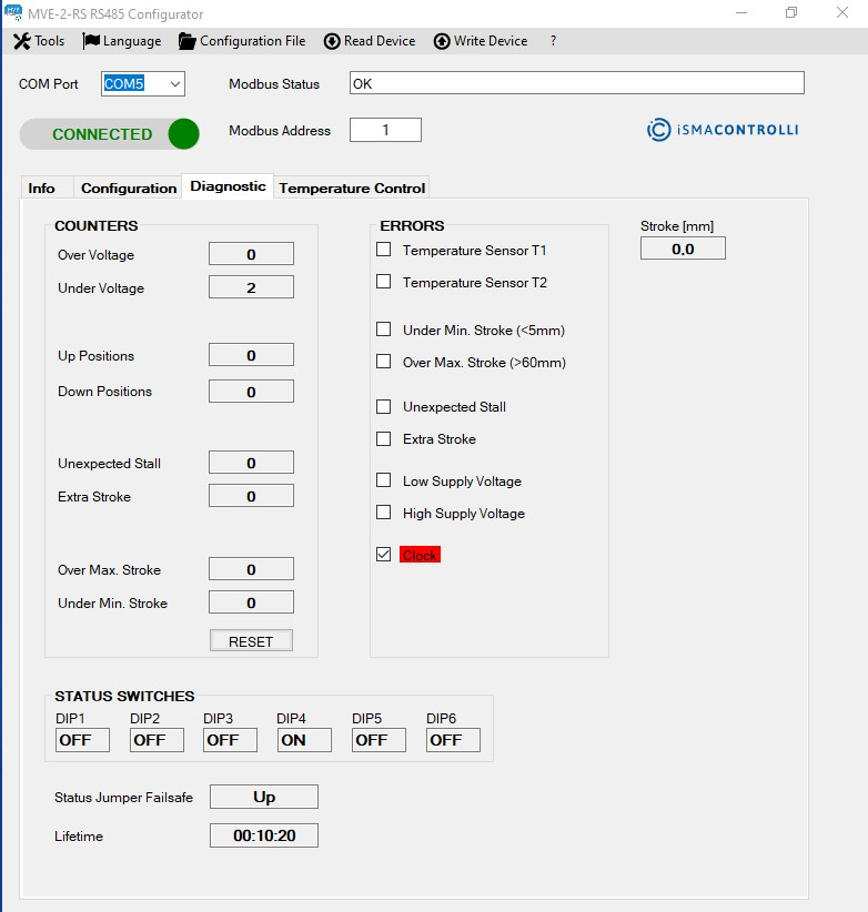
Diagnostic tab
-
Stroke [mm]: shows the value of the actuator stroke calculated in mm during a calibration phase. It is a read-only value.
The COUNTERS section displays the number of events (mainly anomalies) that have occurred in the actuator. The events that can be logged are:
-
Over Voltage: shows how many high voltage supply anomalies have occurred;
-
Under Voltage: shows how many low voltage supply anomalies have occurred;
-
Up Positions: identifies the number of times that the actuator has been fully retracted;
-
Down Positions: identifies the number of times that the actuator has been fully extended;
-
Unexpected Stall: identifies an unexpected stall anomaly; this value represents the number of times that a stall has occurred within the stroke;
-
Extra Stroke: identifies an extra stroke anomaly; this value represents the number of times an extra stroke has occurred compared to the stroke calculated during the last calibration phase (out-of-range stroke);
-
Over Max. Stroke: shows how many stroke anomalies calculated by the actuator in the calibration phase (stroke greater than 60 mm) have occurred;
-
Under Min. Stroke: shows how many stroke anomalies calculated by the actuator in the calibration phase (stroke less than 5 mm) have occurred;
-
RESET: allows to reset all the counters (Over Voltage, Under Voltage, Up Positions, Down Positions, Unexpected Stall, Extra Stroke, Over Max. Voltage, Under Min. Voltage).
The ERRORS section shows the detectable actuator errors:
-
Temperature Sensor T1: the temperature sensor connected to the T1 terminal (supply temperature) has an anomaly (if temperature sensors are required for the enabled functions);
-
Temperature Sensor T2: the temperature sensor connected to the terminal indicated with T2 (return temperature) has an anomaly (if temperature sensors are required for the enabled functions);
-
Under Min. Stroke (<5mm): during the calibration phase, a stroke was calculated below the minimum allowed value;
-
Over Max. Stroke (>60mm): during the calibration phase, a stroke above the maximum allowed value was calculated;
-
Unexpected Stall: the actuator is in an unexpected stall condition in the stroke range;
-
Extra Stroke: the actuator is in an extra stroke condition; therefore, the actuator is in a position beyond the calculated stroke;
-
Low Supply Voltage: the power supply of the actuator is below the minimum allowed threshold (the performance of the actuator is not guaranteed);
-
High Supply Voltage: the power supply of the actuator is above the maximum allowed threshold (the performance of the actuator is not guaranteed);
-
Clock: indicates that the time and date have not been set in the actuator since the last time the actuator was switched on (it is only necessary in the case of using the Energy information). Synchronization is carried out in the Configuration tab as described in the specific paragraph.
Active errors are highlighted in red color.
The STATUS SWITCHES section allows to read the DIP switches configuration set on the actuator.
-
Status Jumper Failsafe: shows the jumper status (up or down) to indicate if the jumper on the emergency return board is inserted or not (it determines the fail-safe direction). The Status jumper fail-safe is applicable only if the Jumper is set on Enabled).
The variables present in this window are read when the Diagnostics tab is clicked from any tab or when the Read Device item from the dropdown menu is clicked, and, also, each time the section title at the top of the corresponding group of information is selected.
Temperature Control Tab
In this window, it is possible to configure and check the parameters of the temperature loop function.
To save the set values, press the Enter key on the keyboard.
The 2 sections in this tab are enabled/disabled (gray color) based on the enabled function in the Configuration tab.
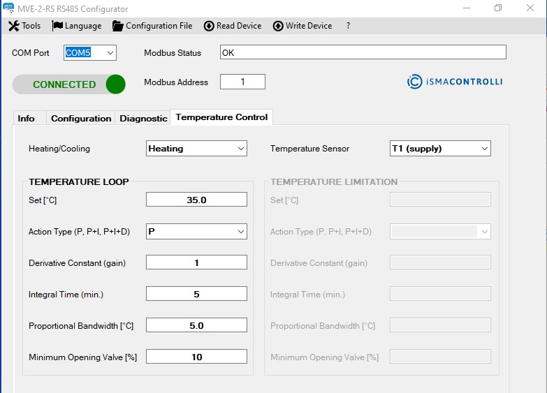
Temperature Control tab
The TEMPERATURE LOOP section allows to set the information for the temperature control functions:
-
Heating/Cooling: sets a cooling/heating mode;
-
Temperature Sensor: sets the temperature sensor (T1 supply, T2 return, or ΔT) to use in the selected temperature function.
The TEMPERATURE LIMITATION section allows to set the parameters for the temperature limitations functions:
-
Set [°C]: represents the temperature setpoint value;
-
Action Type (P, P+I, P+I+D): represents the type of control of the system to be used to regulate the desiderate temperature. To write the selected value into the actuator, press the Enter key on the keyboard;
-
Derivative Constant (gain): represents the contribution of the derivative action;
-
Integral Time [min]: defines the time within which the proportional action is proposed again;
-
Proportional bandwidth ∆T [°C]: represents the temperature error value (error = current temperature value - setpoint temperature), beyond which the valve will be fully open;
-
Minimum Opening Valve [%]: represents the minimum opening valve (expressed as a percentage) necessary to ensure a minimum of flow in the system.
To save a specific value into the actuator, it is required to press Enter key on the keyboard. To save all data, it is possible to click the Write Device option.
It is also possible to invoke an instant reading of the information of the single section by clicking on the label at the top of this section.