Firmware Version and Module Type (30001)
In this register type and firmware version of the module are encoded.
A low byte contains information about the type of module in accordance with the table below:
|
Value |
Type |
|---|---|
|
8110 (0x5116) |
8I |
|
9110 (0x5B16) |
8I-IP |
|
8410 (0x5416) |
8U |
|
9410 (0x5E16) |
8U-IP |
|
8310 (0x5316) |
4I4O-H |
|
9310 (0x5D16) |
4I4O-H-IP |
|
8510 (0x5516) |
4U4O-H |
|
9510 (0x5F16) |
4U4O-H-IP |
|
8610 (0x5616) |
4U4A-H |
|
9610 (0x6016) |
4U4A-H-IP |
|
8210 (0x5216) |
4O-H |
|
9210 (0x5C16) |
4O-H-IP |
|
8710 (0x5716) |
4TO-H |
|
9710 (0x6116) |
4TO-H-IP |
|
5010 (0x3216) |
MIX18 |
|
5110 (0x3316) |
MIX38 |
|
5210 (0x3416) |
MIX18-IP |
|
5310 (0x3516) |
MIX38-IP |
|
8810 (0x5816) |
12O-H |
|
9810 (0x6216) |
12O-H-IP |
|
8910 (0x5916) |
24I |
|
9910 (0x6316) |
24I-IP |
Firmware version and module type
The high byte contains the module firmware version multiplied by 10.
For example:
In the 30001 register, number 1281010 = 0x320A16, which means that it is module MIX18 (0x32) with firmware in version 1.0 (0x0A16 = 1010).
Module Address (30002)
This register contains information about the address of the Modbus module. This address is set with switches S1 and S2 (see section Setting Module Address).
Baud Rate and Protocol (30003)
The register contains information about the baud rate and type of protocol in accordance with the table below. This register reflects the state of S3 switch.
|
Baud rate |
Protocol |
|||||
|---|---|---|---|---|---|---|
|
Bit 0 |
Bit 1 |
Bit 2 |
Baud rate |
Bit 3 |
Bit 4 |
Protocol |
|
0 |
0 |
0 |
User defined |
0 |
0 |
Modbus RTU |
|
0 |
0 |
1 |
76800 |
0 |
1 |
Modbus ASCII |
|
0 |
1 |
0 |
4800 |
1 |
0 |
BACnet Master |
|
0 |
1 |
1 |
9600 |
1 |
1 |
BACnet Slave
|
|
1 |
0 |
0 |
19200 |
|||
|
1 |
0 |
1 |
38400 |
|||
|
1 |
1 |
0 |
57600 |
|||
|
1 |
1 |
1 |
115200 |
|||
Baud rate and protocol
Counter of Received Messages (30004)
The 32-bit register with the number of valid Modbus messages received by the module, which was powered up last. The value is reset after the power cycle or after changing transmission parameters (speed, stop bits, parity, etc.).
Counter of Error Messages (30006)
The 32-bit register with the number of error Modbus messages received by the module, which was powered up last. The value is reset after the power cycle or after changing transmission parameters (speed, stop bits, parity, etc.).
Counter of Sent Messages (30008)
The 32-bit register with the number of Modbus messages sent by the module, which was powered up last. The value is reset after the power cycle or after changing transmission parameters (speed, stop bits, parity, etc.).
Up Time (30012)
This 32-bit register contains module counting time in seconds from the last powering up or module reset.
Hardware Version (30130)
This 16-bit register contains the module hardware version multiplied by 10.
MAC Address (30131)
This 48-bit register contains MAC address information of the module.
Device Actions (40001)
Setting the 40001 register, according to the table below, enables 1 of 4 available actions: module reset, reloading the settings, setting to default, and entering the bootloader.
|
Value |
Action |
|---|---|
|
511 |
Reset |
|
767 |
Reload settings |
|
1023 |
Set to default |
|
1279 |
Enter bootloader |
Device actions
Baud Rate (40136)
If sections 1, 2, and 3 of the S3 switch are in off position, the baud rate is determined in accordance with this register. The baud rate is determined with the following formula:
Baud rate = register value • 10
Stop Bits (40137)
The number of stop bits is determined on the basis of this register in accordance with the following table:
|
Value |
No. of Stop Bits |
|---|---|
|
1 (default) |
1 |
|
2 |
2 |
|
256 |
RS485 biasing* |
Stop bits
* Bit No. 8 activates RS485 biasing resistors in order to pull-up the voltage on the RS485 bus. If the bit no. 8 is true (bit 8 = 1), RS485 biasing resistors are activated. The function is only available in MINI IP I/O modules with hardware version >= 2.0
The biasing resistors are useful in case the iSMA modules are connected with third-party devices with the same RS485 bus and communication errors appear on the network.
WARNING!
Only a single device in the network can have biasing resistors activated!
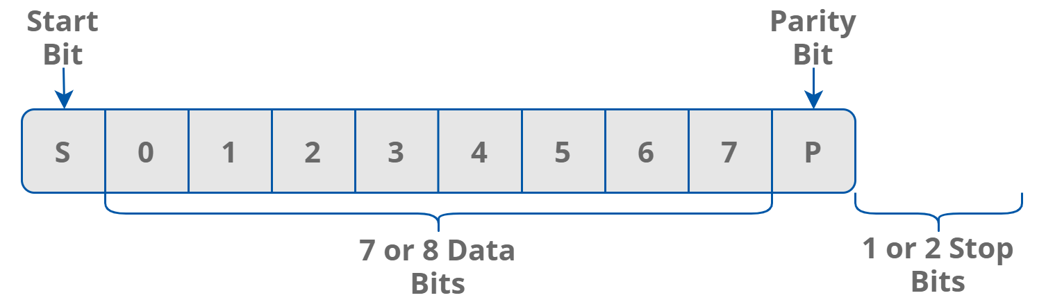
Modbus frame
Data Bits (40138)
The number of data bits transmitted in a single byte is determined according to the following table:
|
Value |
No. of Data Bits |
|---|---|
|
7 |
7 |
|
8 (default) |
8 |
Data bits
Parity Bit (40139)
Every byte of data being transferred may have additional protection in the form of a parity bit added before the stop bit (bits).
The method of calculating the parity bit is presented in the table below:
|
Register Value |
Type of Parity Bit |
|---|---|
|
0 (default) |
None |
|
1 |
Odd (number of all ones in a byte is odd) |
|
2 |
Even (number of all ones in a byte is even) |
|
3 |
Always 1 |
|
4 |
Always 0 |
Parity bit
Response Delay Time (40140)
The value of this 16-bit register determines the number of milliseconds to wait before the unit answers the question. This time is used to extend the interval between the question and answer. The default value of 0 means no delay (the answer is sent once during the transmission of 3.5 character required by the protocol Modbus RTU).
Watchdog Time (40141)
This 16-bit register specifies the time (expressed in seconds) to watchdog reset. If the module does not receive any valid message within that time, all digital and analog outputs will be set to the default state.
This feature is useful in case of an interruption in data transmission, and if, for security reasons, output states must be set to the appropriate state in order to avoid endangering the safety of persons or the property.
The default value is 0 seconds, which means the watchdog function is disabled.
If the watchdog is triggered, the power LED blinks in the specified sequence (3 blinks with 20 Hz frequency and 1-second pause).