iSMA-B-FCU Programming User Manual
Introduction
This user manual describes programming of the iSMA-B-FCU controller.
Revision History
Rev. | Date | Description |
|---|---|---|
1.0 | 20 Dec 2016 | First edition |
1.1 | 20 Aug 2017 | The reason for the creation of the new version of the document:
Changes in Document:
Added: description of Advance Control kit |
1.2 | 27 Jan 2020 |
|
1.3 | 21 Apr 2022 | Rebranded Updated iSMA Room Device kit |
Overview
Each new iSMA-B-FCU device is equipped with the default application, firmware, and kits. The default application can be modified for individual purposes, used with no changes, or the user can create a new, custom application.
Modifying the default application, or creating a new one, can be done only online (in real time), using the SOX protocol and iSMA Tool. The size of application cannot exceed 64 kB. Available memory can be checked in the Mem Available slot (under the Plat component).
Using the FCU Updater, the modified or created application can be downloaded from one iSMA-B-FCU device and uploaded to other iSMA-B-FCU device(s). The iSMA-B-FCU device has two built-in RS485 ports:
- COM1: port with the screw connector; the port can be used for communication using the Modbus RTU/ASCII or BACnet protocol (including BACnet Master-Slave communication);
- COM2: port with two RJ12 connectors; the port can be used for communication using the Modbus Async protocol.
Each iSMA-B-FCU device has a set of kits, which are installed with the firmware. These kits are required for proper operation of default application, and can be also used to develop a custom application. The kits cannot be changed or delayed. The iSMA-B-FCU device is equipped with the following kits:
- sys: the Sedona core system module;
- control: basic function blocks library;
- inet: IP and UDP/TCP socket APIs;
- sox: the Sox service for remote management;
- iSMA_BACnetMasterSlave: the kit for Master-Slave communication.
The iSMA-B-FCU device can work in defined groups, where one device is master and the remaining devices (slaves) follow the master parameters. This way, it is possible to share up to 150 points. This function is available only in the BACnet MS/TP protocol, using the RS485 port (COM1). Each master device can have up to 5 slave devices.
- iSMA_FCU: the kit includes components used to develop the FCU application; it consists of components controlling temperature outputs, fan, etc. ;
- iSMA_ModbusAsyncNetwork: the kit includes components for the Modbus Async communication;
The Modbus Async can be used to communicate with other devices connected to the built-in RS485 port (COM2). It is possible to read/write up to 200 points this way. There is no restriction about the number of connected devices.
- iSMA_platFCU: the kit includes components for all types of inputs and outputs servicing, components for communication with the higher-level system (using Slave Network component), and NV components.
The Slave Network component is used to manage the BACnet MS/TP or Modbus RTU/ASCII protocol, using the RS485 port (COM1). The Slave Network component allows for sharing of up to 200 numeric points and up to 200 Boolean points. A total number of memory cells for NV numeric (and integer) components cannot exceed 200. A total number of memory cells for NV Boolean components cannot exceed 200.
Note: Method of calculating memory cells for NV components is described in the Plat service chapter.
The iSMA-B-FCU device has 18 built-in physical inputs and outputs:
- 4 special inputs;
- 4 digital inputs;
- 3 analog outputs;
- 5 digital outputs;
- 2 triac outputs.
The device is equipped with a S3 - CFG DIP switch, which allows to manage the eight binary signals. Using the DIP switch is recommended to manage the configuration of the device.
The device is also equipped with the alarm LED (ALM), which allows for signalizing states of the iSMA-B-FCU device predefined in the application. For example, it can be used for signalizing alarms.
The components for servicing of all inputs, outputs shown below are placed under the iSMA_platFCU palette.
Programming in iSMA Tool
As a significant part of the end-to-end iSMA solution, the iSMA Tool gives the customer a convenient way to create and manage custom applications for the Sedona-based iSMA controller.
The iSMA Tool covers all requirements to create and manage applications: it has a wire sheet for convenient visual programming, property sheets for details; it offers kits management, real-time monitoring of system states and slots values, logs and historical data, deployment and backup.
iSMA Tool Installation
The iSMA Tool is a software created for modern Microsoft Windows system, such as Windows 10. The oldest supported version of the operating system is Windows 7. The iSMA Tool is delivered as a compressed folder, which needs to be extracted in a chosen location on a hard drive, unless the access to the extracted folder is restricted by the system (e.g., Program Files is not a recommended location).
In order to download the iSMA Tool Software Bundle, which includes all files necessary to run the program efficiently (a zipped file iSMATool_Vx.x.x.zip), go to the iSMA CONTROLLI web page ismacontrolli.com and to the iSMA Tool/Software Bundle folder.
Extracting the zipped package reveals the folders and additional files described below. In order to run the iSMA Tool, open the iSMATool.exe file.
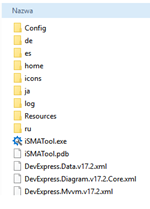
The extracted folders have the following functions:
- Config: a folder containing a record of user’s individual settings regarding windows location and other iSMA Tool work settings, such as a language chosen for the iSMA Tool interface.
- External: a folder containing an API .dll file.
- home: a folder where all the data created by user are saved, i.e., device backups, applications, etc. It is also a folder where the kits library, available the in iSMA Tool, is located.
- icons: a folder with graphical files such as the iSMA Tool interface icons.
- Localization: a folder with the text files providing the iSMA Tool language sources.
- log: a folder, where the logs of the iSMA Tool, which also appeared in Console window, are saved. When contacting iSMA CONTROLLI technical support, it is advised to copy the last file with logs form that folder
- de, es, fr, it, ja, pl, Resources, ru: folders with system libraries.
To properly install and work with the iSMA Tool the computer must meet the following minimal requirements:
- processor (CPU): Intel Core i3-3xxx or equivalent;
- memory: 4GB RAM;
- storage: 50 GB internal hard driver;
- Ethernet 100 Mbit or 1 Gbit NIC;
- MS Windows 7 (recommended MS Windows 10);
- .NET Framework 4.6.2 or higher.
WARNING! If the iSMA Tool is being run for the first time, it asks to accept the EULA license. The license must be accepted to run the program. Failure to do so closes the iSMA Tool.
Note: For the iSMA Tool to work properly it needs to be run periodically at least once a month, on a computer connected to the Internet for about an hour, depending on the data transfer rate. It enables the iSMA Tool to automatically download the latest data, such as kits and updates.
The iSMA Tool is a portable software. It is transferable and it can be installed on a portable data storage device, such as a USB memory stick. It allows the iSMA Tool to be run directly from a portable data storage device on any PC, including offline ones.
Connecting to Device
WARNING! Before starting to program the iSMA-B-FCU device using the SOX protocol, it is recommended to connect the device to 230 V AC power supply.
- Before connecting the iSMA-B-FCU device to the iSMA Tool, run the FCU Updater.
Connect the iSMA-B-FCU device to the USB port in your computer–SOX and Console buttons should be active, which means that the FCU Updater is communicated with the iSMA-B-FCU device.
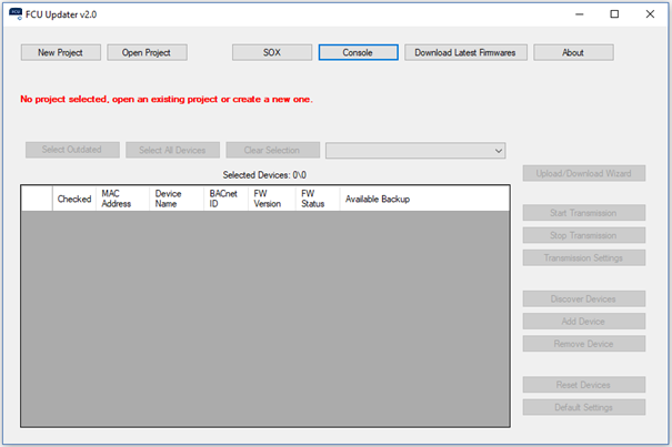
- Click the SOX button to open a pop-up window, and then click the Begin Communication button.

- Open the iSMA Tool.
- In order to connect to the device, select the following options:
Right-click on the project folder and select the Add Device option.
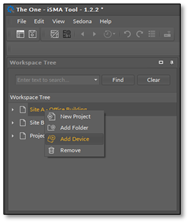
320pxNote: The newest version of the iSMA Tool should be installed on the PC for connection with the newest version of the iSMA-B-FCU.
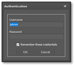
- Upon selecting the above option, an authorization window pops up.
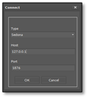
Please enter the following values:
- IP address: 127.0.0.1;
- Port: 1876.
Log in using the following username and password:
- Username: admin;
- Password: empty box (no characters).