The RJ12 socket is designed for connecting external modules, Modbus devices, and room/wall panels. The FCU device has two parallel RJ12 sockets (RS485 interface in a switch mode) with the same pin configuration. These sockets provide communication in the Modbus RTU protocol.
The RJ12 socket provides a power supply dedicated for external room panels with maximum load up to 2.5 W per both sockets. Before connecting devices powered from RJ12, please calculate the power supply load. For example, the power consumption of the LP/Touch Point panels with a temperature sensor, on average, is 0.5 W, so the maximum number of such panels on the bus is 5, while the average power consumption of the FP panels is 0.2 W, so the maximum number of such panels on the bus is 10. It is recommended to connect maximum 5 LP/Touch Point panels working at the same time or 10 FP panels.
Worth to notice:
Connected panels can be freely combined (5 LP panels, or 5 Touch Point panels, or 2 LP panels and 3 Touch Point panels, or 3 Touch Point panels and 5 FP panels etc.). It is important not to exceed a maximum load of 2.5 W for both RJ12 sockets together.
For short distance, up to 100 m, it is recommended to use for connection a standard category 3-, 4-, or 6-wire telephone straight cable without crossing (for example, YTLYP 6x0.12). For longer distance, it is recommended to use a standard twisted shielded Modbus cable.
RJ12 pins in the FCU controller are shown in the figure below.

RJ12 pins
To connect the LP, Touch Point, or FP panel, use the following types of cables:
-
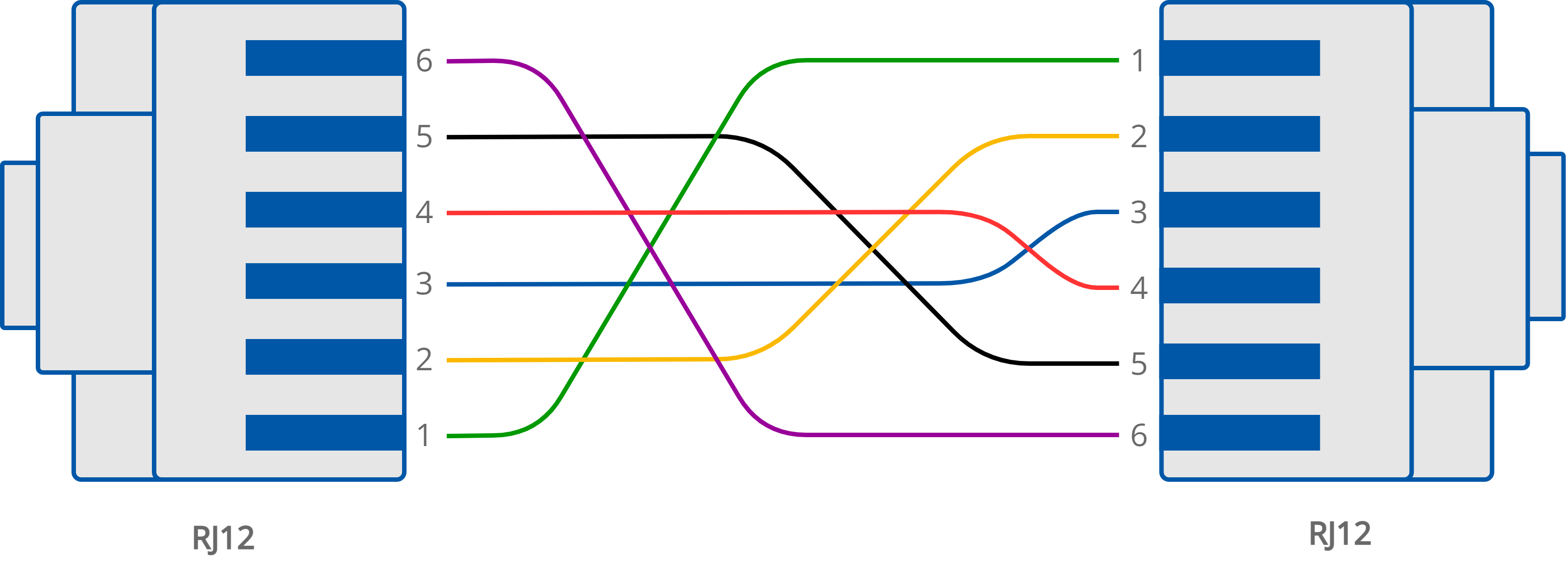
LP: RJ12-RJ12 cable;

RJ12-RJ12 connection of the LP panel
-
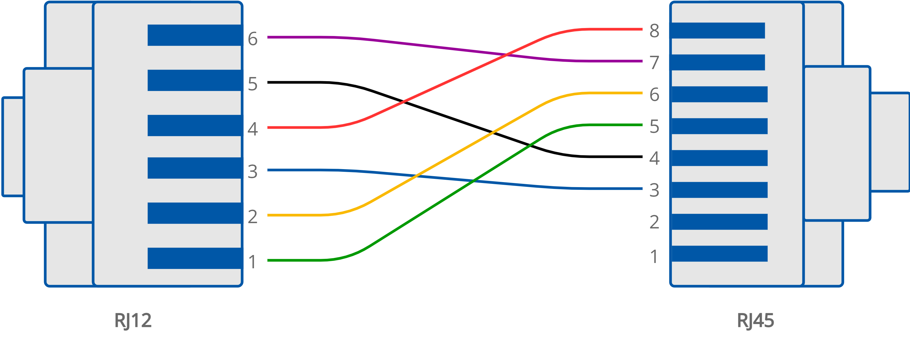
Touch Point: RJ12-RJ45 cable (the Touch Point panel is equipped with RJ45 sockets):

RJ12-RJ45 connection of the Touch Point panel
-
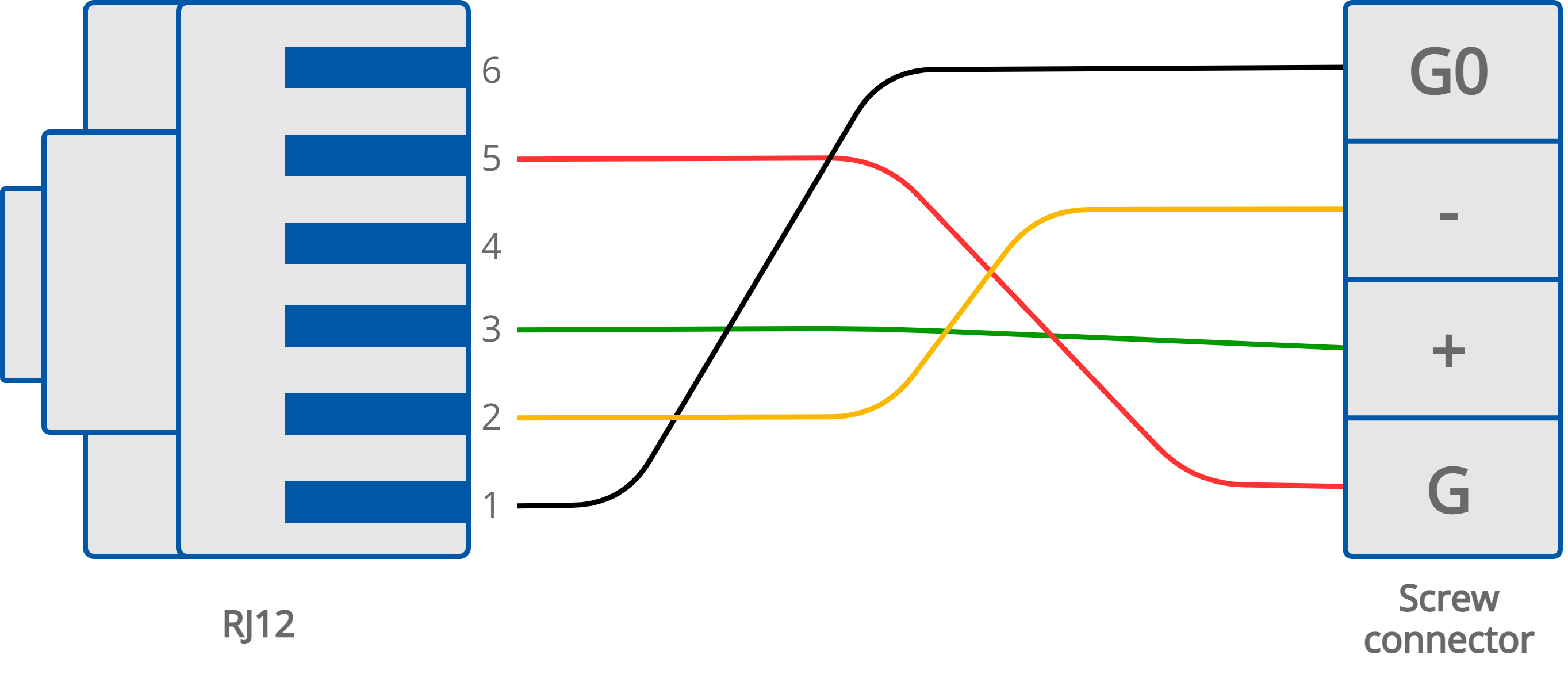
FP: RJ12-screw connector cable (the FP panel is equipped with a 4-pin screw terminal):

RJ12-screw connector connection of the FP panel
