This section outlines all details regarding hardware specification of the Control Point panel.
Panel Versions
|
Model |
Panel Code |
Sensors |
Display |
Color |
|||
|---|---|---|---|---|---|---|---|
|
Temperature |
Humidity |
CO2 |
Yes |
Black |
White |
||
|
Control Point |
CP-DISP-B |
|
|
|
|
|
|
|
CP-DISP-W |
|
|
|
|
|
|
|
|
CP-H-DISP-B |
|
|
|
|
|
|
|
|
CP-H-DISP-W |
|
|
|
|
|
|
|
|
CP-C-DISP-B |
|
|
|
|
|
|
|
|
CP-C-DISP-W |
|
|
|
|
|
|
|
|
CP-HC-DISP-B |
|
|
|
|
|
|
|
|
CP-HC-DISP-W |
|
|
|
|
|
|
|
|
CP-VAV-DISP-B |
|
|
|
|
|
|
|
|
CP-VAV-DISP-W |
|
|
|
|
|
|
|
|
CP-VAV-H-DISP-B |
|
|
|
|
|
|
|
|
CP-VAV-H-DISP-W |
|
|
|
|
|
|
|
|
CP-VAV-C-DISP-B |
|
|
|
|
|
|
|
|
CP-VAV-C-DISP-W |
|
|
|
|
|
|
|
|
CP-VAV-HC-DISP-B |
|
|
|
|
|
|
|
|
CP-VAV-HC-DISP-W |
|
|
|
|
|
|
|
Control Point panel models
Legend:
-
H - a version with temperature and humidity sensors;
-
C - a version with temperature and CO2 sensors;
-
HC - a version with temperature, humidity, and CO2 sensors;
-
B - black version;
-
W - white version.
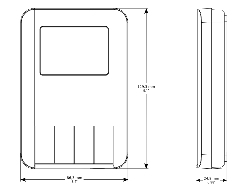
Dimensions [mm]
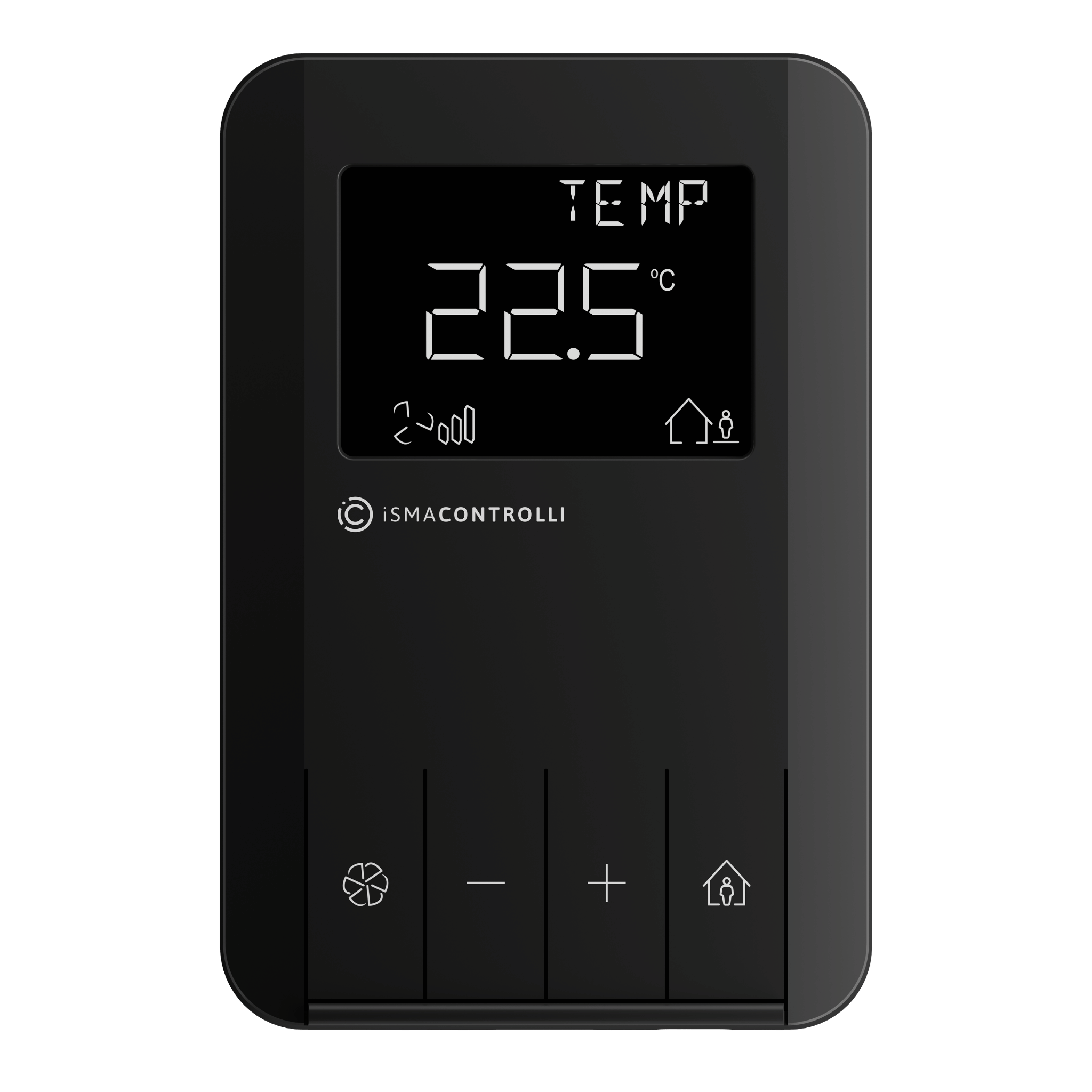
Front Panel
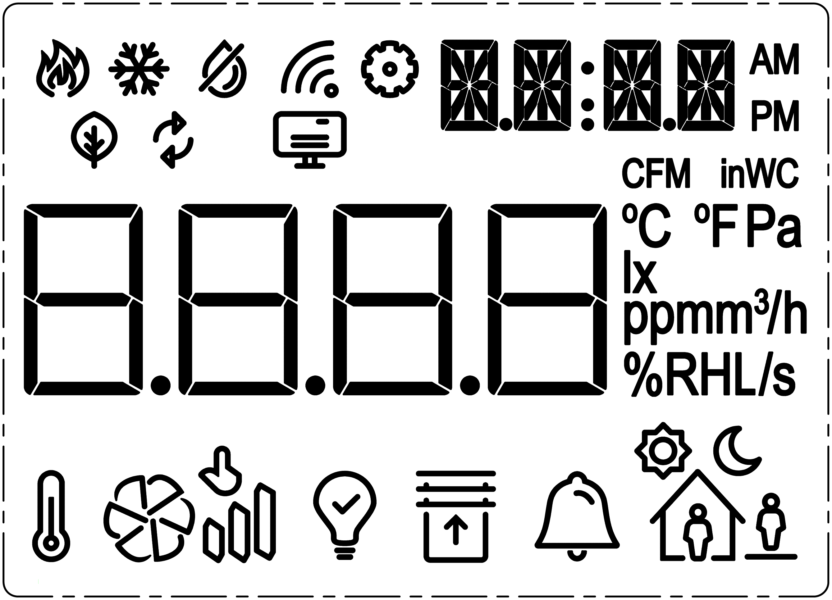
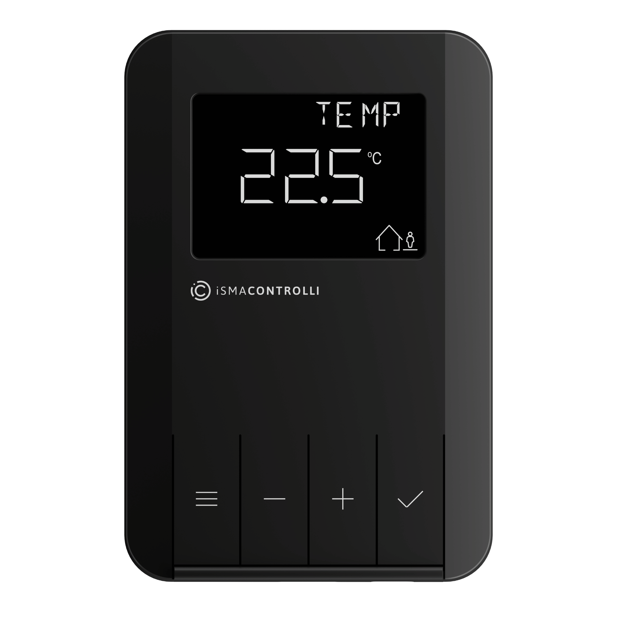
Display
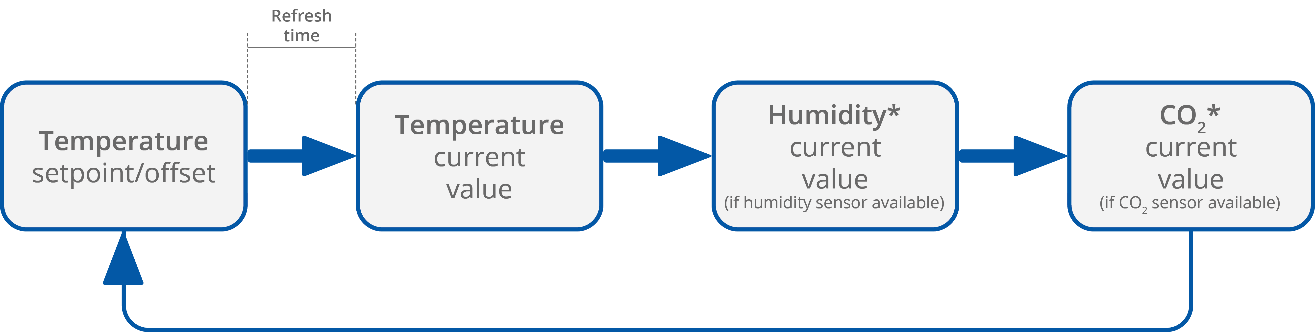
The panel is equipped with an LCD display, which shows the information about:
-
temperature setpoint (after pushing a + or – button, setpoint can be adjusted);
-
temperature current value with unit;
-
humidity current value with unit (optionally);
-
CO2 current value with unit (optionally).
Note: Currently displayed parameters change with a frequency set in the 40217 register.
Depending on the panel’s version, Control Point or Control Point VAV, the display shows different information.
In the Control Point line, the display additionally shows the information about:
-
current fan mode;
-
current occupancy status.
In the Control Point VAV line, the display additionally shows the information about:
-
current occupancy status.
Keypad
|
|
The Control Point panel has 4 functional buttons, which differ between the panel’s Control Point line and the Control Point VAV version.
In Control Point line, the buttons are the following:
-
fan;
-
decrement (-);
-
increment (+);
-
occupancy.
Note: In order to change the fan modes or occupancy status, use the increment/decrement buttons.
In the Control Point VAV line, which has no fan control, the buttons are the following:
-
menu;
-
decrement (-);
-
increment (+);
-
confirmation.
Buzzer
The Control Point panel is equipped with a buzzer, which signalizes each pushing of a button with a sound and/or provides a CO2 alarm function emitting a sound once the CO2 level exceeds a set alarm value. The alarm can be confirmed and muted by pressing any button.
The buzzer may be activated or deactivated using the DEVICE_CONFIGURATION register/object (bit 0, BUZZER for activating/deactivating the buzzer, and bit 6 for activating or deactivating CO2 alarm function).
|
Bit |
Register Value |
Description |
|---|---|---|
|
Bit 0 |
0 |
Buzzer deactivated |
|
1 |
Buzzer activated |
|
|
Bit 6 |
0 |
Buzzer for CO2 alarm deactivated |
|
1 |
Buzzer for CO2 alarm activated |
The BUZZER values
By default, the buzzer is active, and the CO2 alarm buzzer is deactivated.