Inputs and Outputs
The arrangement of inputs and outputs signals described below is dedicated for the AHU application specifically. This configuration cannot be changed without risking an incorrect operation of the AHU application. Most of available sensors are active in the application for specific functionalities depending on the type of sensor, e.g., connecting a mixing temperature sensor impacts a control of mixing dampers. Some of the sensors are indispensable for the operation of the AHU application, depending on the selected configuration, while the rest can be used optionally if additional functionality is required, e.g. a CO2 concentration sensor affecting the control of mixing dampers.
AAC20 Built-in I/O
U1 – Discharge Air Temperature: required to perform a proper discharge air temperature control function, the absence of the sensor does not stop the AHU system, but results in full opening of the heater and exchanger control;
U2 – Return Air Temperature: required to perform the discharge air temperature control based on the return air temperature - only for supply and exhaust air handling units;
U3 – Outside Air Temperature: required to manage summer and winter modes, to introduce compensation to the set temperature, and to perform energy recovery and economizer functions;
U4 – Return Water Temperature: optionally required to maintain the minimum return temperature on the water from the heater (and as preheater) in winter mode, depending on the outside air temperature (lack of sensor means the function is not performed);
U5 – Discharge Air Pressure: optionally required to maintain the set pressure in the air supply duct by controlling the fan speed (lack of sensor means the function is not performed);
U6 – Return Air Pressure: optionally required to maintain the set pressure in the air supply duct by controlling the fan speed (lack of sensor means the function is not performed);
U7 – Energy Recovery Exchanger differential Pressure Switch: absolutely required to protect the exchanger against frosting/icing - active state (close) exceeding the set pressure level disables the use of the exchanger - de-icing function; alternatively, in case of an air handling unit with mixing dampers:
U7 – Return CO2 Concentration: optionally required to ensure the appropriate share of fresh air while maintaining the set level of CO2 concentration in the return air when using energy recovery mixing dampers - no connection does not perform the function;
U8 – Filters status: optionally required to monitor filter contamination, without implementing additional functions;
I1 – Antifreeze Thermostat: absolutely required to protect the preheater against freezing - active (closed) state causes the preheater valve to open to 100% and turns on the preheater pump (always needed);
I2 – (Pre)Heater Pump fault: optionally required, by default, to trigger an alarm condition (active state closed) reporting a (pre)heater failure, it can also be configured in PreHeater parameters as confirmation of the (pre)heater pump operation, which will report a (Pre)Heater Failure after a certain time if the (pre)heater pump is turned on and has not been confirmed operating;
I3 – Fan Run or Fan Belt state: absolutely required to confirm the operation of ventilation as a state from inverters or a state of compression on fans (as control of belts on fans), lack of confirmation after a certain time causes an alarm condition (active open state) reporting a Fans Failure and stops the air handling unit (always needed);
I4 – Operation Switch: required to confirm the permission to operate the air handling unit, for service stop of the air handling unit (always needed);
A1 – (Pre)Heating Valve: control of the (pre)heating valve is calculated as a result depending on the temperature and humidity control (humidification does not allow heating) (always needed);
A2 – Cooling Valve: control of the cooling valve (if allows on the configuration) calculated as a result depending on the temperature and humidity control (as dehumidification);
A3 – Energy Recovery Control: control of the exchanger depending on the configuration - rotational speed, the opening of the bypass/mixing damper, or opening of the valve calculated as a result depending on the temperature and CO2 control (mixing damper);
A5 – Discharge Fan Control: control of the fan speed on the discharge air duct with priority in relation to maintaining the set pressure in the discharge air duct. In the absence of a pressure sensor, it depends on temperature control, humidity control, CO2 control, and manual setting;
A6 – Return Fan Control: control of the fan speed on the return air duct with priority in relation to maintaining the set pressure in the return air duct. In the absence of a pressure sensor, it depends on temperature control, humidity control, CO2 control, and manual setting;
O1 – Dampers Command: command to open/close isolated dampers (outside and exhaust);
O2 – Fans Command: common command to start discharge & return fans (typical start command for inverter);
O3 – (Pre)Heater Pump Command: command for the switch on/off (pre)heating pump;
O4 – Energy Recovery Command: command depending on the configuration for the switch on/off wheel unit or twin-coil pump.
Extensions
Due to the wide range of AHU implementations, in addition to the base unit, the AAC20 controller, an extension module, iSMA-B-4U4A or -MIX18, can be added as necessary. The extension module must be equipped with the Modbus communication set, with address 1 and baud rate of 115200 kbps.
4U4A-H
Configuration
Configuration of the module's communication and inputs and outputs is carried out in the iSMA Configurator software.
The required communication settings are as follows:
Actual baud rate: 115200 bps;
MAC Address: 1;
Protocol Type: Modbus RTU.
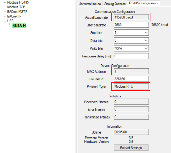
Modbus configuration of the iSMA-B-4U4A-H extension module
The required inputs settings are as follows:
U1: disable resistance input;
U2: disable resistance input;
U3: resistance input;
U4: 10K3A1 NTC B-3975K (°C).
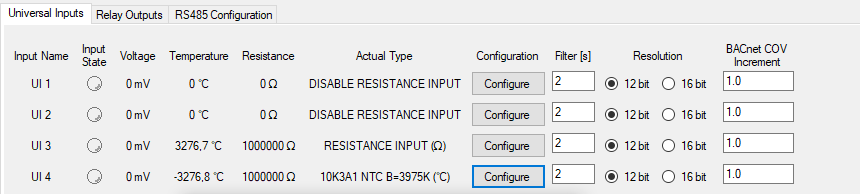
Inputs configuration of the iSMA-B-4U4A-H extension module in the iSMA Configurator
Outputs are required to be set as default.
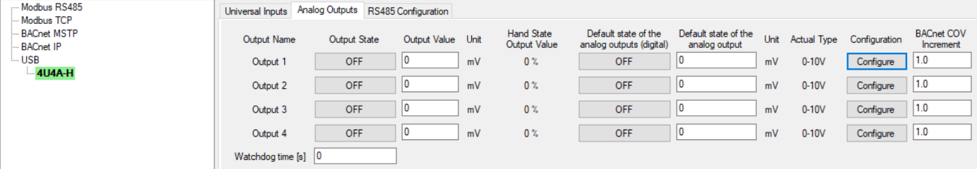
Configuration of analog outputs in the iSMA-B-4U4A-H module in the iSMA Configurator
Functional I/O Specification
The list below describes sensors and signals supported by the AHU application, indicating which of them are absolutely required, in what configurations, and those which are optional:
U1 – Discharge Air Humidity: required to perform the discharge air humidity control function - for supply-exhaust and supply air handling units;
U2 – Return Air Humidity: required to perform the discharge air humidity control based on the return air humidity - only for supply and exhaust air handling units;
U3 – Humidifier fault: optionally required, by default, to trigger an alarm condition (active state closed) reporting a humidifier failure, it can also be configured in Humidifier parameters as confirmation of the humidifier operation, which will report a Humidifier Failure after a certain time if the humidifier is turned on and has not been confirmed operating. With the MINI version, it is also possible to connect a Hygrostat signal - in parallel or instead from a humidifier;
U4 – ReHeater Pump fault: optionally required, by default, to trigger an alarm condition (active state closed) reporting a reheater failure, it can also be configured in ReHeater parameters as confirmation of the reheater pump operation, which will report a Reheater Failure after a certain time if the reheater pump is turned on and has not been confirmed operating;
A1 – Humidifier Control: control of the humidifier (if allows on the configuration) calculated as a result depending on humidity control;
A2 – Reheating Valve: control of the reheating valve (if allows on the configuration) calculated as a result depending on the temperature and humidity control (as dehumidifacation);
A3 – Humidifier Command: command for the switch on/off humidifier (depending on configuration - 1 water humidifier the switch on/off depending on the request, 2 - steam humidifier permanent switch on if AHU is running);
A4 – ReHeater Pump Command: command for the switch on/off preheating pump.
MIX18
Configuration
Configuration of the module's communication and inputs and outputs is carried out in the iSMA Configurator software.
The required communication settings are as follows:
Actual baud rate: 115200 bps;
MAC Address: 1;
Protocol Type: Modbus RTU.
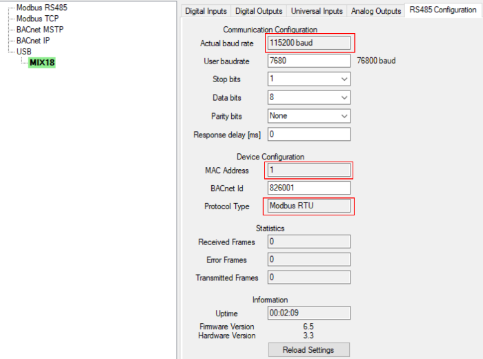
Modbus configuration of the iSMA-B-MIX18 extension module
The required inputs settings are as follows:
U1: disable resistance input;
U2: disable resistance input;
U3: 10K3A1 NTC B-3975K (°C);
U4: 10K3A1 NTC B-3975K (°C);
U5: disable resistance input.
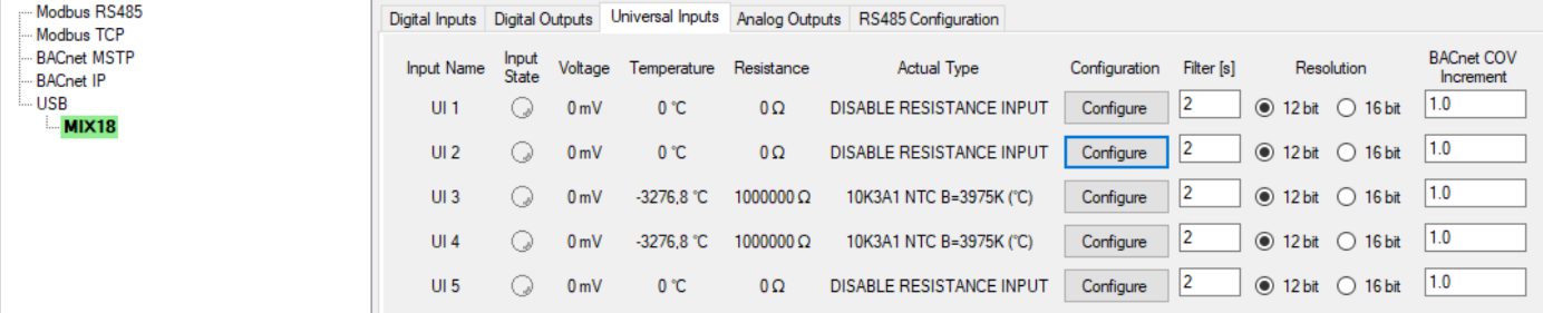
Inputs configuration of the iSMA-B-MIX18 extension module in the iSMA Configurator
Outputs, analog and digital in MIX18, are set as default. Analog outputs are presented below:
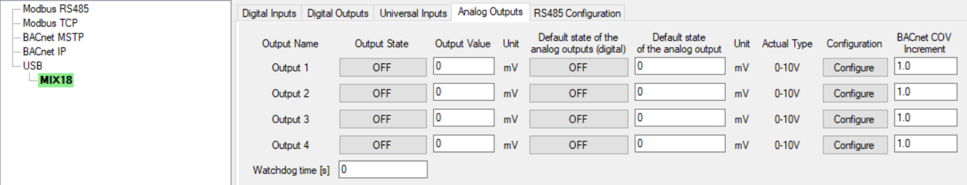
Configuration of analog outputs in the iSMA-B-MIX18 module in the iSMA Configurator
Functional I/O Specification
The list below describes sensors and signals supported by the AHU application, indicating which of them are absolutely required, in what configurations, and those which are optional:
U1 – Discharge Air Humidity: required to perform the discharge air humidity control function - for supply-exhaust and supply air handling units;
U2 – Return Air Humidity: required to perform the discharge air humidity control based on the return air humidity - only for supply and exhaust air handling units;
U3 – Cooling Limit Temperature: optionally required to control the minimum temperature level behind the cooler in air dehumidification mode;
U4 – Mixing Temperature: optionally required to control the minimum temperature level behind the mixing damper depending on the Outside Air Temperature;
U4 – Medium Temperature: optionally required to control the minimum level of medium temperature on the pipe of the twin-coil exchanger depending on the outside air temperature;
U4 – Exhaust Air Temperature: optionally required to control the minimum temperature level behind the wheel and cross-flow exchanger depending on the outside air temperature;
U5 – Outside Air Humidity: optionally required to perform economizer function;
I1 – Humidifier fault: optionally required, by default, to trigger an alarm condition (active state closed) reporting a humidifier failure, it can also be configured in Humidifier parameters as confirmation of the humidifier operation, which will report a Humidifier Failure after a certain time if the humidifier is turned on and hasn’t confirmed;
I2 – ReHeater Pump fault: optionally required, by default, to trigger an alarm condition (active state closed) reporting a reheater failure, it can also be configured in ReHeater parameters as confirmation of the reheater pump operation, which will report a Reheater Failure after a certain time if the reheater pump is turned on and hasn’t confirmed;
I3 – Hygrostat: required as protection against excessive humidification (flooding), exceeding the set humidity level (actively closed state) disables the humidification function;
I4 – Energy Recovery fault: optionally required, by default, to trigger an alarm condition (active state closed) reporting an energy recovery unit or pump failure, it can also be configured in Exchanger parameters as confirmation of the energy recovery unit or pump operation, which will report an Energy Recovery Failure after a certain time if the energy recovery unit or pump is turned on and hasn’t confirmed;
I5 – Manual Reset: optionally required (for MIX18), allows after configuring (default use an auto resetting function) use for manual resetting of alarms;
A1 – Humidifier Control: control of the humidifier (if allows on the configuration) calculated as a result depending on humidity control;
A2 – Reheating Valve: control of the reheating valve (if allows on the configuration) calculated as a result depending on the temperature and humidity control (as dehumidification);
A3 – Humidifier Command: command for the switch on/off humidifier (depending on configuration - 1 water humidifier the switch on/off depending on the request, 2 - steam humidifier permanent switch on if ahu is running);
A4 – ReHeater Pump Command: command for the switch on/off preheating pump;
O1 – Fans Failure Alarm: optionally required, collective alarm common for both fans to be used as LED signalling on the front of the control cabinet;
O2 – Heater Pumps Failure Alarm: optionally required, collective alarm common for both heater pumps to be used as LED signalling on the front of the control cabinet;
O3 – Energy Recovery Failure Alarm: optionally required, collective alarm for the energy recovery exchanger (depending on configuration) to be used as LED signalling on the front of the control cabinet;
O4 – Humidifier Failure Alarm: optionally required, collective alarm for the humidifier to be used as LED signalling on the front of the control cabinet.