Heater (Preheater or Reheater)
The Heater module provides modulating control of the heating coil valve actuator and can be selected for a heater or preheater and reheater. A damper enables a signal to be set if the coil’s return water condition is normal.
The module has inputs for;
the heating control signal (HTS);
return water temperature (RWT);
heating pump status (HPumpStatus);
and frost protection (FEZ).
The outputs are:
heating valve (HTV);
heating pump command (HPU);
pump-off alarm fail-to-command alarm (ALARM);
and damper enable signal (DME).
Pump-off or fail-to-command alarms can be generated, provided that the pump status is connected. Pump and valve exercise is part of the module.
Note: RWT and FEZ do not apply to reheater.
Damper Enable Output
On start-up, the heating valve and pump assume normal control. When the outside air temperature is below the limit, which is defined by parameter OAT_FrostProtection, the return water temperature RWT should reach the calculated return water temperature setpoint (minus ½ RWT_P_band), before the damper enables signal DME to be set to on. This feature reduces the risk of frost damage on initial plant start-up. If the time, to reach the mentioned temperature, exceeds the delay, defined by parameter DME_OnDelay, DME will be active.
Note:
As long as the outside air temperature is below the value of parameter OAT_FrostProtection and the coil return water temperature sensor is not present, the damper will be enabled after the delay, as defined by parameter DME_OnDelay.
As long as the outside air temperature is below the value of parameter OAT_FrostProtection and return water temperature sensor is not present, the valve will be set to parameter HTV_FrostProt_ValveUp and is returned to its normal control position via a ramp function defined by parameter HTV_Ramp.
As long as the outside air temperature is above the value of parameter OAT_FrostProtection plus the fixed differential of 1K, the delay to enable DME will be ignored.
Modulating Control of Valve Actuator
The module can work in several configurations. In a typical sequencing application, the module will receive a heating control signal (HTS) from the control module. The HTS can be selected, defined by parameter HTS_RatioEnable, to be either as a position signal Y or as a correction signal X, both within a range of 0-100%.
In the case of a Y signal, the input is transferred directly to the valve output as shown in the next figure.
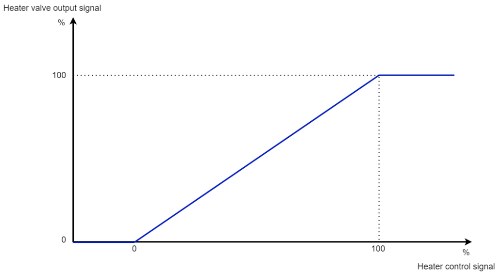
Heater output signal
In the case of an X signal, the signal sent to the valve output varies from 0-100% over a sub-range of the X signal, determined by a ratio sequence with start and stop points, defined by parameters HTS_StartRatioControl and HTS_StopRatioControl.
Selection of Heating Coil Type
The coil type can be selected by parameter HeaterMode as a heater, or a preheater & a reheater, as shown in the next figure.

Coil type
The coil type defines how the heating valve controls according to humidification and dehumidification as shown in the next table.
Heater Mode | Type | Humidification | Dehumidification |
|---|---|---|---|
Heater (1 on LCD) | Heater | Controlled by temperature | Controlled by temperature |
PreHeater and ReHeater (2 on LCD) | Preheater and reheater | Preheater controlled by temperature, reheater closed | Preheater closed, reheater controlled by temperature |
Return Water Temperature Control
Minimum Temperature Control
If the heating coil works as a heater or preheater, optionally the coil can be equipped with a coil return water temperature sensor to protect against undesired low temperatures. If this sensor is available a minimum return water temperature setpoint can be calculated. This setpoint is outside air temperature compensated between the values, defined by parameters OAT_MaxSetpoint and OAT_MinSetpoint, in order to override the valve output to open.
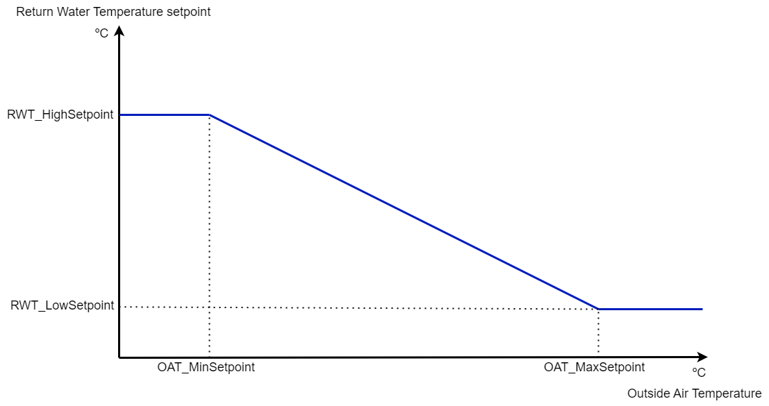
Return water temperature setpoint according to the outside air temperature
Note: this minimum return water temperature control is only active when the outside air temperature is lower than the value of parameter OAT_FrostProtection.
Depending on the calculated setpoint and the P-band, defined by parameter RWT_P_band, the control output varies from 0-100% as shown in the next figure.
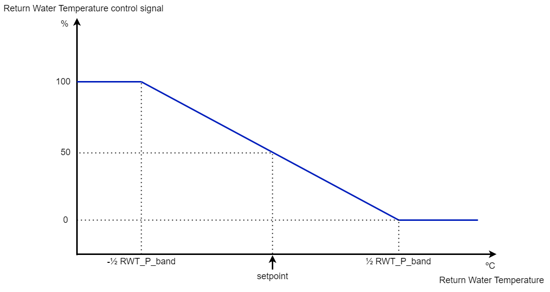
Return water control signal according to the return water temperature
Maximum Temperature Control
The coil return water temperature RWT is also limited by a maximum setpoint, as defined by parameter RWT_MaxSetpoint, in order to override the heating valve output to close if the return water temperature becomes too high (this function is required in case of district heating applications).
If return water temperature is present, then the temperature control with the highest demand controls the valve.
Frost Protection
To protect the heating coil against freezing a frost alarm procedure is started as soon as a frost alarm condition occurs. If the frost alarm condition is returned to the normal position a frost recovery procedure starts.
Frost alarm procedure:
If a frost alarm occurs the following actions will be executed:
The pump starts.
The heating valve gets a predefined position, according to the value of parameter HTV_FrostProt_ValveUp.
If a coil return water temperature sensor is available, the return water temperature setpoint is set to the value of parameter FEZ_RWT_SptUp.
Frost recovery procedure:
When the frost alarm condition returns to normal, the following actions will be executed:
If a coil return water temperature sensor is available, the return water temperature setpoint, raised by the value in parameter FEZ_RWT_SptUp, is returned to its normal control value via a ramp function defined in FEZ_SetupRamp.
The ramp function to normal control is shown in the next figure.

Ramp function for return water temperature setpoint
If no sensor (return water) is available, the predefined valve position, defined by parameter HTV_FrostProt_ValveUp, is returned to its normal control position via a ramp function defined in HTV_Ramp, as shown in the next figure.
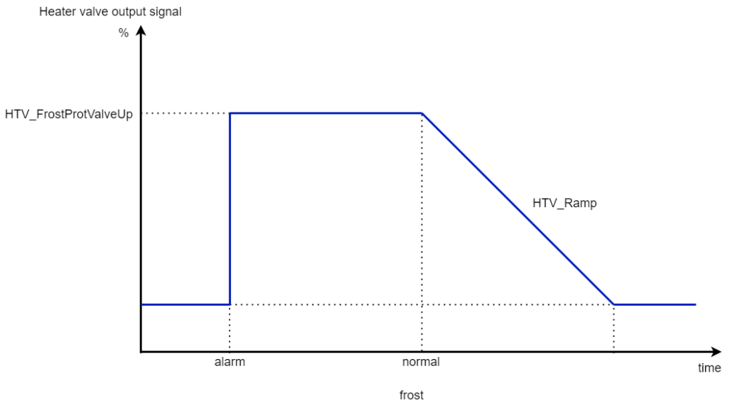
Ramp function for heater valve output (without RWT sensor)
Pump Control
If the parameter HPU_Enable is set to True, the pump is enabled. In this case, the pump starts when the heating valve opens more than 3% (fixed), and stops after an adjustable delay, defined by parameter HPU_OffDelay, when the heating valve output value goes below 1% (fixed). The pump runs continuously if the outside air temperature is below the value in parameter OAT_FrostProtection or in case of a frost alarm condition (Thermostat=True), even if the power demand program has commanded the air handling unit off.
During initial start-up, the pump starts after a delay, defined by the parameter HPU_OnDelay.
Pump Alarms
If the pump status (HPumpStatus..) is connected pump-off or fail-to-command alarms are generated. The pump alarms are delayed as defined by the parameter HPU_StatusAlarmDelay. When a pump-off alarm occurs and the outside air temperature is below the value of parameter OAT_FrostProtection, the air handling unit will be switched off. This function can be enabled by the parameter DME_EmergencyStop.
Selection of Alarms or a Fail-to-command Alarm
With the parameter HPU_StatusAlarmDelay, it is possible to select different kinds of alarms, as shown in the next table.
HPU_StatusAlarmDelay setting | Alarm output behaviour |
|---|---|
> 1 | The status is monitored and differentiated off-alarms are generated, after the delay of parameter HPU_StatusAlarmDelay |
= 1 | The status input will be handled as a failure input without delay (a logic 1 at the input means a failure condition) |
= 0 | No monitoring is done and no alarms are generated |
< 0 | The status is monitored and a fail-to-command alarm is generated at the on-alarm output, after the (absolute) time of the delay, defined by parameter HPU_StatusAlarmDelay |
Periodic Pump and Valve Exercise
This exercise is done in sequence by commanding the internal variable Pump_Exercise (for pump and valve in Inputs section), by default, it is run every week on Sunday (internal variable DayOfWeek in the Inputs section) at 1am (internal variable ExerciseHour in the Inputs section). The pump on and valve open time is defined by the parameter HPU_Pmp_Vlv_Exercise (this value should not be smaller than the valve actuator runtime).
It is possible to disable pump and valve exercises, as shown in the next table.
HPU_Pmp_Vlv_Exercise setting | Pump and valve exercise behavior |
|---|---|
> 0 | Both pump and valve exercises will be executed |
= 0 | No pump and valve exercise will be executed |
< 0 | Only pump exercise will be executed |
If the Pump_Exercise command is given and the pump is off, the pump will start. After a delay, defined by parameter HPU_Pmp_Vlv_Exercise, the pump will stop and the valve will be opened to 100% during the time of parameter HPU_Pmp_Vlv_Exercise. If the pump runs and the Pump_Exercise command is given no pump test will be done, but as soon as the pump stops the valve test will be executed, as shown in the next figure.

Pump and valve exercise
AHU Stops on Pump-off Alarm at Low Outside Air Temperature
If the outside air temperature is below the value of parameter OAT_FrostProtection and the pump would fail, which means that no adequate frost protection can be done, the total AHU will be stopped when parameter DME_EmergencyStop was set to the value of True.
In this specific case, the module will disable its DME output immediately.
Tips:
Sometimes, the preheater consists of more than one individual heating coil, each one with its own control valve. In this case, a separate module should be applied for each heating coil and the coils should be sequenced by setting the ratio function active, inside the respective parameter lists to decide the HTS signal in several sequence ranges. For instance, when there are four coils, the first one works from 0-25%, the second one from 25-50%, the third one from 50-75%, and the last one from 75-100% (of the HTS-signal).
It is also possible that the preheater is designed too small (on purpose, in order to get better controllability) and the reheater has to be used in addition to the preheater, or in case of the need for reheating when water spray humidification is used and the supply air has to be reheated. In this case, the same trick can be done: Enable the ratio function only in the parameter list of the preheater and set its ratio values for instance from 0-50% (of the HTS-signal). The heater mode should be defined as a preheater and a reheater coil so it works all the time when heating is needed independent of the HumMode. There is no need to enable the ratio function within the reheater because it should work on the full range of the HTS signal (0-100%).