Fans
The Fans module can be used wherever there is a requirement for variable speed control of a fan. It can be used for supply fans as well as for exhaust fans and incorporates plant override mode signals.
The module also provides filtering of the duct static pressure. The duct static pressure is filtered to provide a smoothed value, which is used to eliminate sudden duct static pressure variations and thus provides a more stable operation of the duct static pressure control.
The module has inputs for:
duct static pressure sensor (DSP);
fan control signal (FCS) from the Control module;
duct static pressure control;
fan pressure switch (FanDiffPressure);
operation switch;
and fan enable signal (FNE) from the damper control.
The fan speed control between minimum and maximum limits is adjustable by parameter settings. Fan speed changes are always ramped up and down.
The module has outputs for:
fan on/off (FansCmd);
variable speed control for discharge and return fans (DischFan, RetFan);
and fan belt alarm (ALARM).
Fan Enable Input
On initial start-up after the fan enable signal (FNE) is true, or after a power failure, there is a delay defined by parameter FSC_OffOnDelay, after which the fan release signal is energized and the fan can start. The fan control signal (FCS) to the variable speed controller will be ramped to the fan speed in accordance with the fan speed control output (FSC) and to the maximum fan speed defined by parameter FSC_MaxSignal, if necessary. This fan control signal (FCS) can come from the Control module and the duct static pressure control. The ramp-up time is adjustable by the parameter FSC_Ramp and occurs when the fan goes to a higher speed. Ramping up and down will always take place in percent per minute.
Fan Speed Control Output (FSC) Ramped up After Start-up
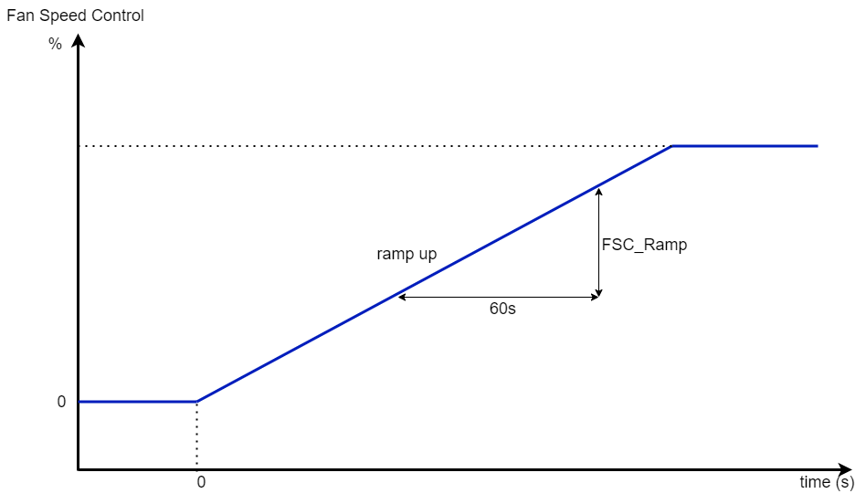
The fan speed control output of the duct static pressure control module will be only once ramped up in percentage per minute, as defined by parameter FSC_Ramp, from zero to the desired controlled level, as shown in the next figure.

Ramp function for fan speed control at start-up
Note: The control signal of the Duct static pressure control has higher priority than Fan speed control and will be omitted from the FSC output of the module if duct pressure sensors are disconnected.
Fan Speed Control
The variable fan speed control from 0% to 100% can be adjusted between minimum and maximum limits as defined by parameters FSC_MinSignal and FSC_MaxSignal. In a typical sequencing application, the module will receive a fan control signal (FCS) from the Control module.
Adjustable Ramp-up and -down of the Fan Speed
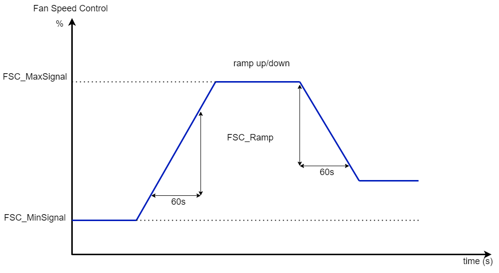
During normal operation, the fan speed changes from a lower speed to a higher or opposite according to the fan speed control FSC. The speed changes are always ramped up and down in percent per minute and defined by parameter FSC_Ramp and limited to the maximum speed defined by parameter FSC_MaxSignal as shown in the next figure.

Ramp function for fan speed control
Setpoint Ramp-up/-down
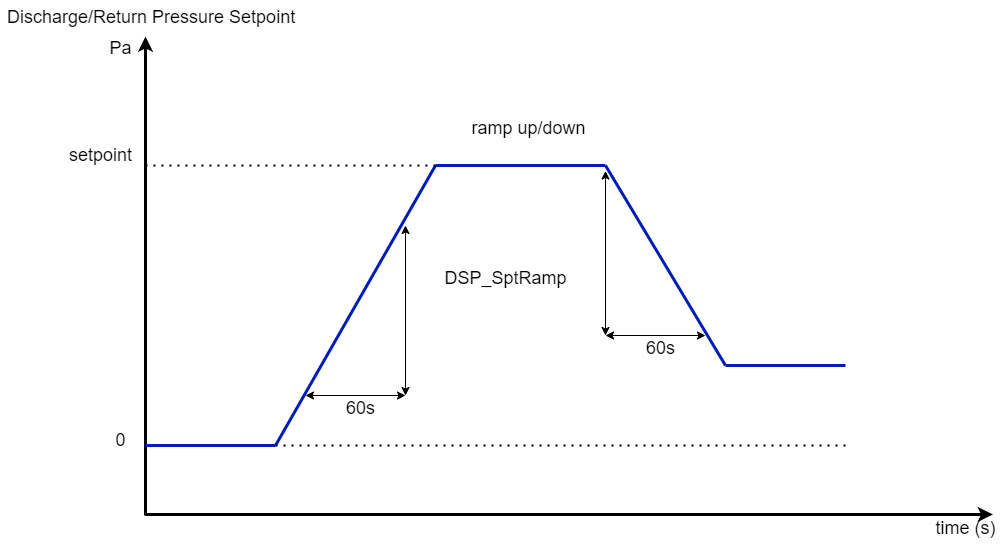
On initial start-up, after the fan enables signal FNE to become true, the setpoint of the duct static pressure control will be ramped up, in Pa per minute, from zero to the value of the desired setpoint, as it is defined by the setpoints DischPressSpt & RetPressSpt. When during normal operation the setpoint of the duct static pressure is lowered, a ramp-down function will be effective. Both ramping-up and ramping-down are defined by the parameter DSP_PressSptRamp, as shown in the next figure.

Ramp function for pressure setpoint
Duct Static Pressure Control
During plant modes 1 to 6, the duct static pressure control will be released as soon as the input FNE becomes true. The setpoint for the duct static pressure control is defined by the internal setpoints DischPressSpt & RetPressSpt, while the proportional band and integral time respectively are defined by the parameters DSP_PressDisP_band, DSP_PressRetP_band and DSP_PressDisI_time, DSP_PressRetI_time. For plant modes 1 to 3 both setpoints are reduced by multiplying with the same parameter for both DSP_NightReduce.
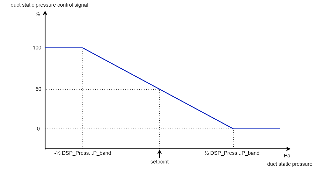
The next figure shows the internal control signal of the duct static pressure control in relation to its setpoint and proportional band.

Static duct pressure control signal according to the static duct pressure
Fan Alarms
There is one alarm output available:
Fan_BeltAlarm is an internal variable.
Note: The delay of the fan belt alarm is defined by the parameter FDP_BeltAlarmDelay. The fan belt alarm can be disabled by setting the value of parameter FDP_BeltAlarmDelay to the value of 0.
Manual/Automatic Reset
In case of an automatic reset (FSC_ManualReset=True), the fan outputs FansCmd, DischFan, and RetFan will stay energized when a fan belt alarm occurs. This is contrary to the manual reset selection (for MIX18 only, FSC_ManualReset=False), where these outputs will always be turned off.
To restart the fan after an alarm occurred, the panel-mounted reset button must be depressed. This button (connected to a Reset input) is brought into the software and further handled as the internal variable Reset.
If there is no push button fitted, parameter FSC_ManualReset should be set to the mode automatic reset.
Operation Switch
The purpose of the operation switch input is to allow for a controlled shut-down and restart procedure of the fan. Typically normally closed contacts from a local isolator next to the fan motor will be used. When the local isolator is switched off, the input OperationSwitch will be False and the outputs DischFan & RetFan and FansCmd will be de-energized. When the local isolator is switched back on and input OperationSwitch becomes True again, the plant can be restarted.
