Exchanger
The Exchanger module provides modulating control of different types of energy recovery equipment and incorporates a plant mode override signal. This module handles 5 selectable types of energy recovery equipment: air-liquid-air with glycol or water as a liquid medium, mixing dampers (using dampers module), heat wheel, and air-to-air plate heat exchanger. The purpose of all these systems is to recover energy from the exhaust air into the incoming outside air of an AHU. This can be used in air handling systems for heating as well as for cooling or a combination of both and results in energy savings.
The module has inputs for:
energy recovery control signal (ERS) from the control module;
outside air temperature (OAT);
return air temperature (RAT);
energy recovery temperature (ERT);
pump/wheel status (ERStatus);
and differential pressure switch (ERdiffPressure).
The outputs are:
energy recovery control command (ERC);
energy recovery pump/wheel (ERP);
pump/wheel off;
or fail-to-command alarm (ALARM).
Selection of Energy Recovery System Type
This module can be used for different energy recovery systems. The system types of energy recovery systems are selectable by the configuration parameter EnergyRecovMode and are as follows:
EnergyRecovMode | Energy recovery system type |
|---|---|
Wheel (1 on LCD) | Type 1: heat wheel |
Cross Flow (2 on LCD) | Type 2: air-to-air plate heat exchanger |
Mixing Dampers (3 on LCD) | Type 3: mixing dampers |
Twin Coil & Return Pump (4 on LCD) | Type 4: air-liquid-air with glycol as liquid medium |
Twin Coil & Supply Pump (5 on LCD) | Type 5: air-liquid-air with water as liquid medium |
The air-liquid-air system (type 4) with glycol as a liquid medium has a pump in the return pipe of the exhaust air coil and the air-liquid-air system (type 5) with water as a liquid medium has a pump in the return pipe of the outside air coil. The glycol application is mostly used in cold climates. The energy recovery systems are equipped with temperature sensors, which are connected to inputs, respectively :
outside air temperature sensor (OAT). This sensor is mounted in the outside air duct;
return air temperature sensor (RAT). This sensor is mounted in the return air duct at the inlet side of the energy recovery air coil;
energy recovery temperature sensor (ERT). This sensor is mounted in the liquid part of the air-liquid-air energy recovery system (types 4 and 5). It is mounted into the return pipe of the exhaust air coil for a glycol system or into the return pipe of the outside air coil for a water system. If this sensor is not available, freeze protection is not possible.
In the case of air-liquid-air twin coils, filled with water, it is not necessary to install and connect the differential pressure switch because freeze protection will be done on the medium and there is no possibility that the exhaust coil will freeze.
Freezing of the exhaust coil will only be possible if the twin-coil system is filled with glycol, so in this case, the differential pressure sensor (ERdiffPressure) is needed.
Start-up
On initial start-up of the AHU or after a power failure, the energy recovery system will be enabled before the energy recovery assumes normal control after a delay, defined by parameter ERP_OnDelay.
Control of the Energy Recovery System
The module can work in several configurations. In a typical sequencing application, the module receives an energy recovery control signal (ERS) from the control module. The ERS can be selected by parameter ERS_RatioEnable, to be either as a position signal Y or as a correction signal X, both with a possible range of 0-100%.
In the case of a Y signal, the energy recovery output signal with minimum and maximum limitation values, defined by parameters ERS_MinRecovery and ERS_MaxRecovery, will command the heat wheel (type 1) or will be transferred directly to the valve output in an air-liquid-air (type 4 and 5) system as shown in the next figure.
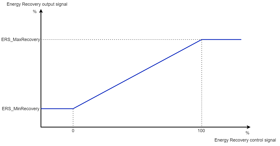
Energy recovery output signal
In the case of an X signal, the output signal varies from 0-100% over a sub-range of the X signal, determined by ratio sequence start- and endpoint parameters, defined by parameters ERS_StartRatioControl and ERS_StopRatioControl, and limited by minimum and maximum values, defined by parameters ERS_MinRecovery and ERS_MaxRecovery, as shown in the next figure. The endpoint parameter must always have a higher value than the start point parameter.

Energy recovery output signal with correction
Control Operation
In system types 1 (heat wheel) and 2 (air-to-air plate heat exchanger), the ERT input can be used to connect a freeze protection low limit sensor, mounted in the exhaust air duct.
In system types 4 and 5, the ERT sensor is mounted in the liquid system to maintain a minimum liquid temperature for freeze protection. The setpoint of the liquid temperature will be calculated against the outside air temperature, defined by parameters OAT_MaxSetpoint and OAT_MinSetpoint. The minimum and maximum values of the setpoint are limited by the parameters ERT_MinSetpoint and ERT_MaxSetpoint, as shown in the next figure.
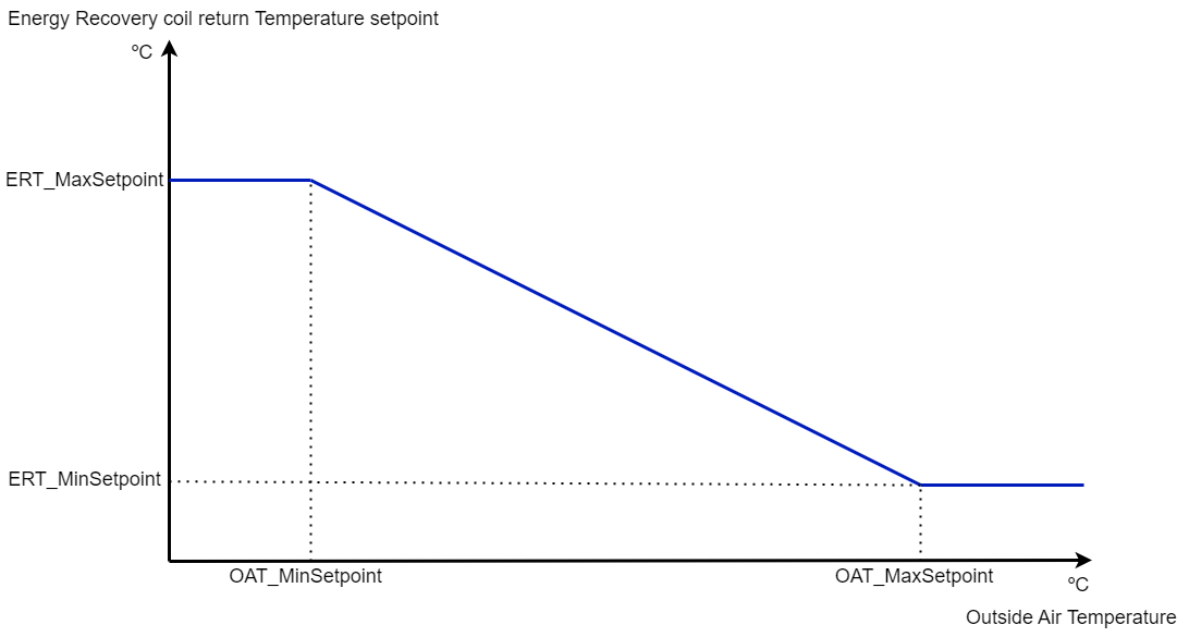
Energy recovery temperature setpoint
Depending on the system type, this module calculates the actuator position of system type 4 (air-liquid-air system with glycol), system type 1 (heat wheel), or system type 2 (air-to-air plate heat exchanger) as shown in the next figure.
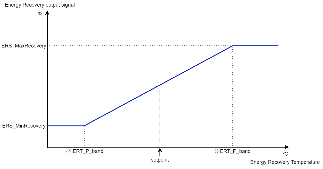
Energy recovery output according to the energy recovery temperature
In system type 5 (air-liquid-air, filled with water), the calculated actuator position is reversed.
Pump Command or Wheel Release
The energy recovery pump in system types 4 and 5 or the heat wheel (type 1) is enabled when the energy recovery control output is more than 3% (fixed) and will be switched off after a delay, defined by parameter ERP_OffDelay when the control signal value is below 1% (fixed). The pump or heat wheel is also enabled if the outside air temperature is below the value of parameter OAT_FrostProtection or during the pump exercise. In system type 1 (heat wheel) the output to the wheel can be selected, continuously or by plant mode override, as defined by parameter ERP_WheelRelease.
Pump/Wheel Alarms
In system types 1, 4, and 5 fail-to-command, the pump-/wheel-off alarms are generated if the pump/wheel status is connected.
Selection of Alarms or a Fail-to-command Alarm
With the parameter ERP_StatusAlarmDelay (delay status alarm) it is possible to select different kinds of alarms, as shown in the next table.
ERP_StatusAlarmDelay setting | Alarm output behavior |
|---|---|
> 1 | The status is monitored and differentiated off-alarms are generated, after the delay of parameter ERP_StatusAlarmDelay |
= 1 | The status input will be handled as a failure input without delay (a logic 1 at the input means a failure condition) |
= 0 | No monitoring is done and no alarms are generated |
< 0 | The status is monitored and a fail-to-command alarm is generated at the on-alarm output, after the (absolute) time of the delay, defined by parameter ERP_StatusAlarmDelay |
Pump and Valve Exercise
This is done in sequence by commanding the internal variables Pump_Exercise (for pump and valve in Inputs section), by default, it is run every week on Sunday (internal variable DayOfWeek in the Inputs section) at 1am (internal variable ExerciseHour in the Inputs section). The pump on and valve open time is defined by the parameter ERP_Pmp_Vlv_Exercise (this value should not be smaller than the valve actuator runtime).
It is possible to disable pump and valve exercises, as shown in the next table.
ERP_Pmp_Vlv_Exercise setting | Pump and valve exercise behavior |
|---|---|
> 0 | Both pump and valve exercises will be executed |
= 0 | No pump and valve exercise will be executed |
< 0 | Only pump exercise will be executed |
If the Pump_Exercise command is given and the pump is off, the pump will start. After a delay, defined by parameter ERP_Pmp_Vlv_Exercise, the pump will stop and the valve will be opened to 100% during the time of parameter ERP_Pmp_Vlv_Exercise. If the pump runs and the Pump_Exercise command is given no pump test will be done, but as soon as the pump stops the valve test will be executed as shown in the next figure.

Pump and valve exercise
Differential Pressure Protection
In system types 1, 2, 4, and 5, a differential pressure switch (ERdiffPressure) is available for safety reasons. When this switch activates, the ERC output signal of the different energy recovery system types will be according to the positions, as shown in the next table.
ER system type | ERdiffPressure off (=false ) | ERdiffPressure on (=true ) |
|---|---|---|
1 | Control | 0% |
2 | Control | 0% |
4 | Control | 0% |
5 | Control | 100% |