Cooler
The Cooler module provides modulating control of the valve actuator of the cooling coil from air handling units, with plant and humidity mode override signals.
The module has inputs for the cooling control signal (CCS), and dehumidification control signal (DEH).
Cooling output signal
The output (CCV) is a 0-100% control signal to the actuator of the cooling coil valve. The valve can be forced to a closed position if the outside air temperature is too low. A valve exercise is part of the control logic.
Modulating Control of the Valve Actuator of the Cooling Coil
The module can work in several configurations. In a typical sequencing application, the module receives a cooling control signal either as position signal Y or correction signal X from the control module, both with a possible range of 0-100%.
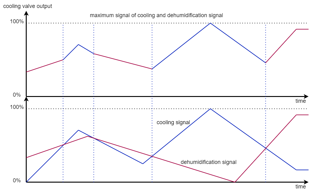
In case of a Y signal the signal will be transferred directly to the valve output. The decision for cooling or dehumidification is already made in the Control module. If for some reason a separate dehumidification input DEH is used, then the module will transfer the highest of the two signals (cooling or dehumidification) to the cooling valve output.
In the case of an X signal, which can be enabled for temperature or dehumidification control, respectively defined by parameters CCS_RatioEnable and DEH_RatioEnable, the signal sent to the valve output varies from 0-100% over a sub-range of the -X- signal, determined by ratio sequence start and end parameters, respectively CCS_StartRatioControl/CCS_StopRatioControl and DEH_StartRatioControl/DEH_StopRatioControl, as shown in the next figure.
Note: The end parameter must have a higher value than the start parameter.
Also in this case the cooling coil module transfers the highest of the two signals (cooling or dehumidification) to the valve output.
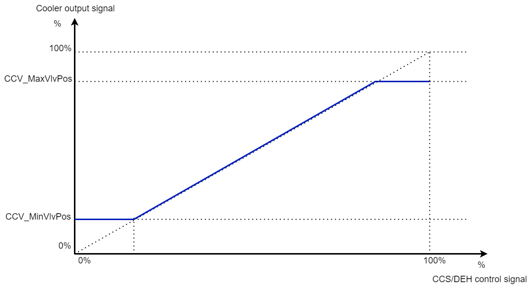
Cooler output signal
Minimum and Maximum Limits for the Actuator Position Signal
The minimum and maximum valve positions during control are defined by the parameters CCV_MinVlvPos and CCV_MaxVlvPos. Limitation of the valve position is mostly needed when DX-expansion valves are used (see previous figure).
Cooling Disabled on Humidification
Cooling is disabled during humidification when the HUM_Mode signal from the Humidifier module equals -1-. This function is selectable by the parameter CCV_CoolOnHumDisable.
Cooling Disabled Based on the Outside Temperature
If the outside air temperature is below a certain value, e.g. 10-14 °C and there is no need for either cooling or dehumidification, the valve can be forced to a closed position. The value is defined by the parameter OAT_CoolerLowLimit and has a fixed differential of 1K.
Note: To disable this function set parameter OAT_CoolerLowLimit to a value of -50°C.
Ramped Opening of the Valve at the Cooling Start
On plant start-up and each time the valve opens from 0%, the actual valve output signal is ramped open to its calculated position during a delay, defined by parameter CCV_VlvRamp, as shown in the next figure. This is done to prevent excessive disturbance of the load of the chiller, caused by a sudden increase in chilled return water temperature. The function is also useful when controlling cooling coils by 2-way valves with a high-pressure cooling medium.
Note: To disable this function set the value defined by parameter CCV_VlvRamp to 100%.
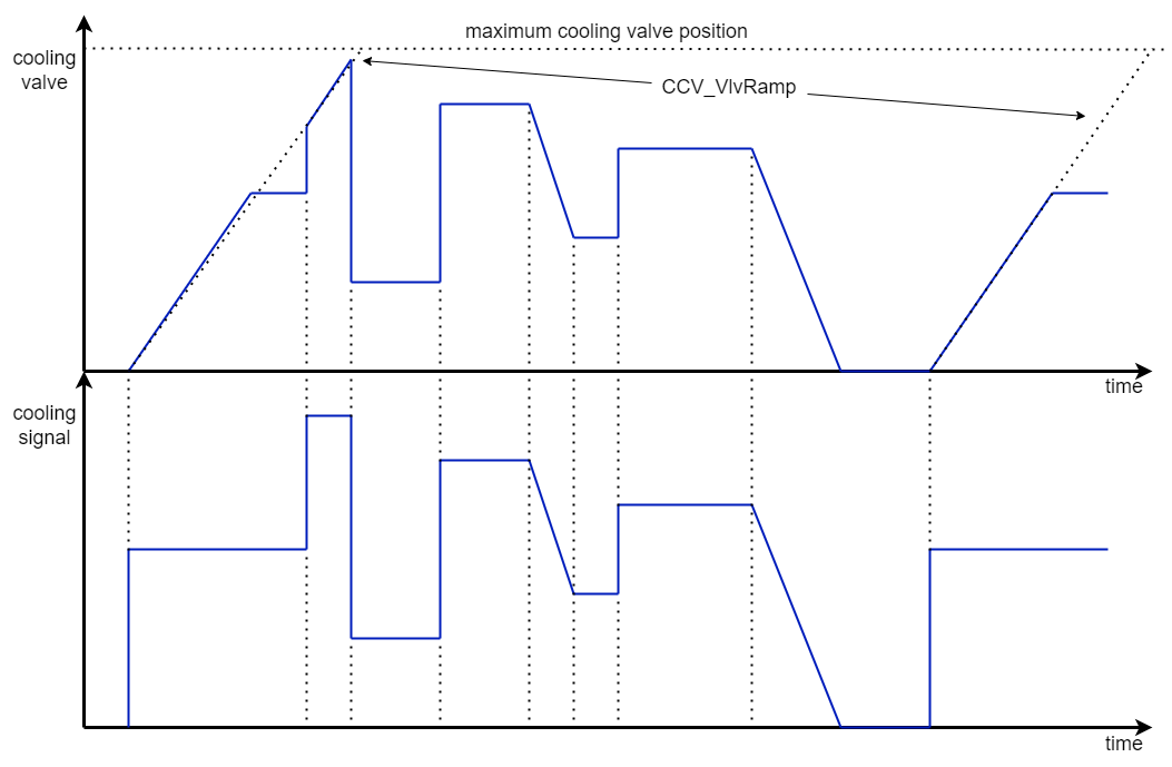
Ramp function for cooling valve
Periodic Valve Exercise
When the plant is off, this exercise is done in sequence by commanding the internal variable Valve_Exercise (for valve in Inputs section), by default, it is run every week on Sunday (internal variable DayOfWeek in the Inputs section) at 1am (internal variable ExerciseHour in the Inputs section). The valve open time is defined by the parameter CCV_Vlv_Exercise, which value should not be less than the valve actuator runtime.
Note: If parameter CCV_Vlv_Exercise is set to -0-, the valve exercise will be disabled.
Minimum Limit Override Control
In this case, the CCS is connected to the cooling signal of the control module. The input CoolLimTemp will be used as a low-limit sensor. The absolute minimum setpoint is defined by the parameter LIM_Setpoint, the proportional band by parameter LIM_P_band and the integral time by parameter LIM_I_time. After start-up, when the PlantMode code equals a value 1, 2, 4, 5 and the FanDiffPressure input becomes true (= 1), the limitation control starts as a P controller. After a delay equal to the I-time, the integral part will be activated.
The following diagrams show the high-limit control signal with PI- and P-control.
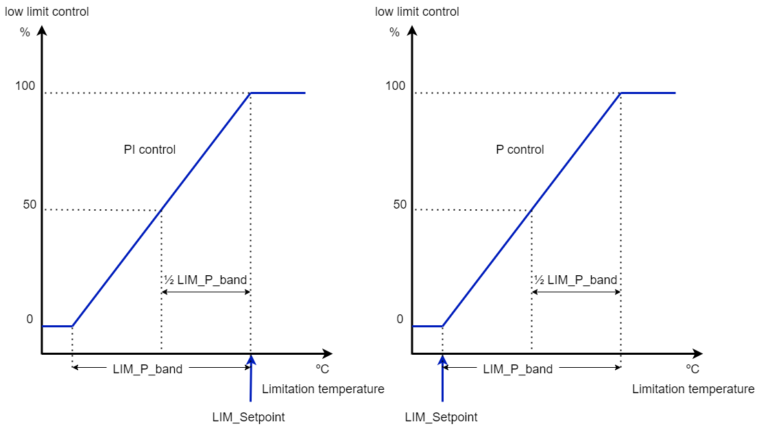
Low limit control with PI- and P-control according to the limitation temperature
Note: If a limitation sensor is connected, the maximum of the two control signals CoolLimTemp and CCS will be used to calculate the CCV value.