Control
The module provides the control for an air handling unit. The module has inputs for:
outside air temperature (OAT);
discharge air temperature (DAT);
room or return air temperature (RAT);
air quality signal (CO2);
manual operation switch condition (OS), and
fan enable signal (FNE).
The respective outputs are signals for:
heating control (HTS);
cooling control (CCS);
energy recovery control (ERS);
dampers control (DMS),
fan speed control (FSC);
dehumidification (DEH);
air quality controls (CO2).
The following internal inputs are included in this module:
PlantMode (from Plant Schedule);
TempSpt;
CO2Setpoint;
DEH_Mode (from Humidifier);
HUM_Mode (from Humidifier);
AbsHumOverride (Economizer);
EnthalpyOverride (from Economizer).
Start Procedure on Initial Start-up to Prevent Frost Alarm
On the initial start of the air handling unit, this application prevents start-up problems and provides frost protection. The heating coil valve and dampers must be in the right positions before the fan(s) can start and all other output signals are released to their normal positions.
To assure a smooth start-up at low outside air temperatures (below OAT_FrostProt), the AHU with mixed air dampers starts on forced recirculation during the time of parameter MAD_RecircTimeStart, when the Plant Mode changes to occupied period or extended operation (4 or 5).
If during start-up the outside air temperature is below the value of parameter OAT_FrostProt, the AHU discharge air temperature setpoint will be raised temporarily by a value, defined by parameter DAT_SptRamp, as soon as the period of forced recirculation has elapsed. Then, it will be ramped down again to its normal setpoint within the time defined by parameter DAT_SptDecTime.
Integral Time Enable Delay After Start-up
After the AHU has been started, both temperature controllers for a room and discharge air temperature will be only proportional controllers during the time, defined by parameter DAT_I_time. After this I-enable delay, the integral functions will start with a value of 0, to assure a smooth start-up.
Types of Temperature Control
Depending on the setting of the parameter TempCtrlMode, the module offers different types of control:
Cascade control (TempCtrlMode as Cascade Temp [1])
Discharge air temperature control with room temperature reset, using both room temperature and discharge air temperature sensors, providing the possibility of PI-control on the room temperature as well as on the discharge air temperature. Sequencing of the output signals for heating, dampers/energy recovery, and cooling. Fan speed is controlled, based on the room temperature deviation with pressure holding priority if present. CO2 (air quality) override on the dampers and/or fan speed.
Constant DAT control (TempCtrlMode as Constant Disch Temp [2])
Constant discharge air temperature control, using only the discharge air temperature sensor, provides PI control on the discharge air temperature. CO2 (air quality) override on the dampers and/or fan speed.
Comfort zone cascade control (TempCtrlMode as Comfort Zone Temp [3])
Discharge air temperature control with room temperature reset and room temperature comfort zone, using both room temperature and discharge air temperature sensors. The P-controller for the room temperature control sequences the output signals of the dampers/energy recovery equipment within the comfort zone. Outside the comfort zone, setpoint adjustments will be provided for the discharge air temperature and fan speed. For plant modes 1 to 3 calculated comfort zone increases fourfold. Two PI controllers for discharge air temperature control. Fan speed can be controlled, based on the room temperature deviation with pressure holding priority if present. CO2 (air quality) override on the dampers and/or fan speed.
Cascade Control (TempCtrlMode as Cascade Temp [1])
Discharge air temperature and fan speed control with room/return air temperature reset. For this function, it is absolutely necessary to have a temperature sensor connected to the input ReturnTemp of the module. The discharge air temperature setpoint and fan speed are shifted by the room temperature deviation. The room temperature setpoint can be reset by the OAT because of the summer compensation. The application uses one room temperature PI-controller to sequence the discharge air temperature setpoint and the fan speed.
The P-band and the I-time of the room temperature controller are respectively defined by parameters RT_P_band and RT_I_time. The P-band and I-time of the discharge air temperature controller are respectively defined by parameters DAT_P_band and DAT_I_time. The discharge air temperature setpoint is always limited by the low and high-temperature values as defined by parameters DAT_LowSetpoint and DAT_HighSetpoint.
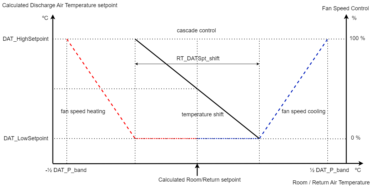
Cascade control
Note: With this cascade control (TempCtrlMode=1), it is also possible to create a control type, based on room temperature with min. and max. limitation of the discharge air temperature. To do so, the room temperature P-band (RT_P_band) can be increased to a value of e.g. 4K (value 25), while the I-time (RT_I_time) must be set to a rather high value, e.g. 3600 seconds (value 0.03). Now there is no fixed relation between the discharge air temperature and the room temperature deviation, only the DAT limits will always be effective.
Sequential Control of the Output Signals, Based on Discharge Air Temperature
In the Control module, the sequencing of all output control signals can be defined. The respective output signals are destined for heater, dampers/energy recovery, and cooler. With the parameters DAT_-Start - DAT_-End the start- and the end-point of each output signal can be adjusted, based on discharge air temperature control, as shown in the next example.
Note: The end-point parameters must always have a higher value than the start-point parameters. If both start- and end-point parameters are set to 0, then that particular sequence function will be inactive.
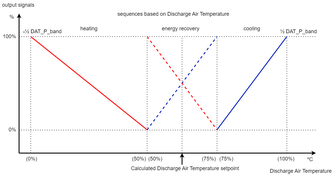
Sequences based on discharge air temperature
Constant DAT Control (TempCtrlMode as Constant Disch Temp [2])
Constant discharge air temperature control with winter compensation, but without room temperature reset. The discharge air temperature is PI-controlled with a setpoint, defined by the value of the internal variable TempSpt. In this case, the minimum and maximum discharge air temperature limits, respectively defined by parameters DAT_LowSetpoint and DAT_HighSetpoint, will be ignored.
Comfort Zone Cascade Control (TempCtrlMode as Comfort Zone Temp [3])
Control with room / return temperature reset and room/return temperature comfort zone, providing:
cascade control of DAT;
fan speed control;
sequence control of dampers or energy recovery equipment.
Cascade Control of DAT
Discharge air temperature control with room/return temperature reset and comfort zone. For this function, it is absolutely necessary to have a temperature sensor connected to the input ReturnTemp of the module. The discharge air temperature setpoint and fan speed are shifted by the room temperature deviation. The room temperature setpoint can be reset by the OAT because of the summer compensation.
The application uses one P-controller for the room temperature, to reset the setpoints for the two discharge air temperature PI-controllers (heating and cooling) in order to sequence the discharge air temperature and the fan speed, with respect to the comfort zone between, which is defined by parameter RT_ComfortZone. For Plant Mode 1 to 3 calculated comfort zone increases fourfold. With parameter RT_DATSpt_shift the respective end-points of the discharge air temperature setpoint-shifting for heating and cooling can be adjusted.
The P-band for the room temperature P-controller is defined by the parameter RT_P_band.
Note: With this type of control, the integral time for the room temperature controller, defined by parameter RT_I_time, will be automatically set to 0.
The next figure shows the comfort zone around the compensated room temperature setpoint and the way the room temperature deviation affects the discharge air temperature setpoint.
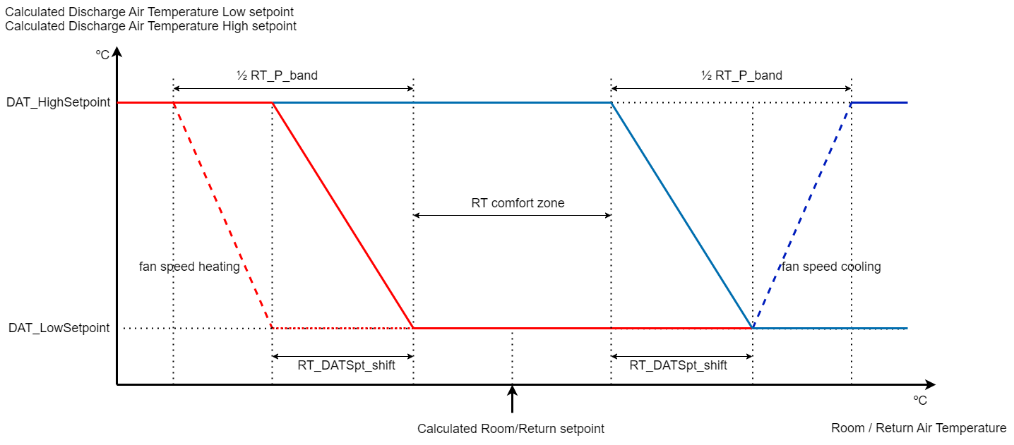
Discharge air temperature setpoint according to room/return air temperature
The P-band and I-time adjustments for both discharge air temperature controllers are respectively defined by parameters DAT_P_band and DAT_I_time. Each controller uses ½DAT_P_band as P-band.
The discharge air temperature setpoint is always limited by the low and high-temperature values as defined by the parameters DAT_LowSetpoint and DAT_HighSetpoint.
Minimum Discharge Air Temperature Control
The minimum discharge air temperature controller uses the discharge air temperature sequencer, defined by the parameters DAT_-Start-DAT_-End. The output signals of the sequencer are used to override the heating, dampers/energy recovery, and cooling control signals.
When the discharge air temperature becomes below the minimum discharge air temperature setpoint, defined by DAT_LoSpt, then the cooling coil will be closed first, the energy recovery control signal will be raised/dampers will be closed and finally, the heating coil will be opened. This prevents the opening of the heating coil, while the dampers are still open. (The room temperature controller controls dampers). The next figure shows the minimum discharge air temperature override sequencer.
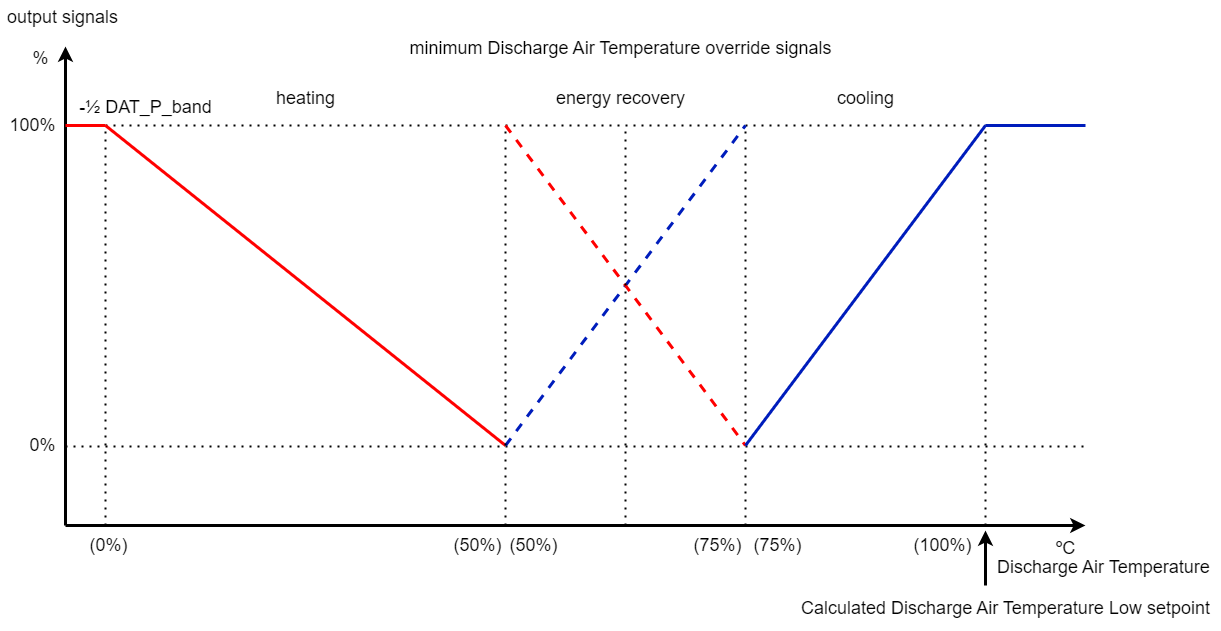
Minimum discharge air temperature override sequencer
Note: The end-point parameters must always have a higher value than the start-point parameters. If both start- and end-point parameters are set to 0, then that particular sequence function will be inactive.
Maximum Discharge Air Temperature Control
The maximum discharge air temperature controller uses the discharge air temperature sequencer, defined by the parameters DAT_-Start-DAT_-End. The output signals of the sequencer are used to override the heating, dampers/energy recovery, and cooling control signals.
When the discharge air temperature becomes above the maximum discharge air temperature setpoint, defined by DAT_HiSpt, then the heating coil will be closed first, the damper control signal will be raised/energy recovery will be closed and finally, the cooling coil will be opened. This prevents the opening of the cooling coil, while the dampers are not fully open. (The room temperature controller controls dampers). The next figure shows the maximum discharge air temperature override sequencer.
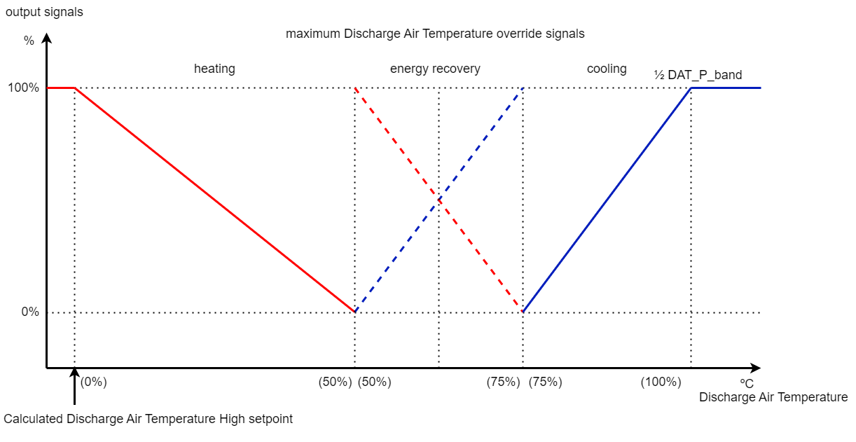
Maximum discharge air temperature override sequencer
Note: The end-point parameters must always have a higher value than the start-point parameters. If both start- and end-point parameters are set to 0, then that particular sequence function will be inactive.
Fan Speed Control
Control of fan speed, based on room/return temperature comfort zone (TempCtrlMode=3). For this function, it is absolutely necessary to have a temperature sensor connected to the input ReturnTemp of the module. The fan speed output signal FSC can be controlled between 0-100%, depending on the room/return temperature deviation outside the comfort zone, as defined by parameter RT_ComfortZone. For Plant Mode 1 to 3 calculated comfort zone increases fourfold.
With parameter RT_DATSpt_shift the respective start-point of the fan speed sequencing for heating and cooling can be defined, as a partition of the half-proportional band RT_P_band of the room temperature P-control.
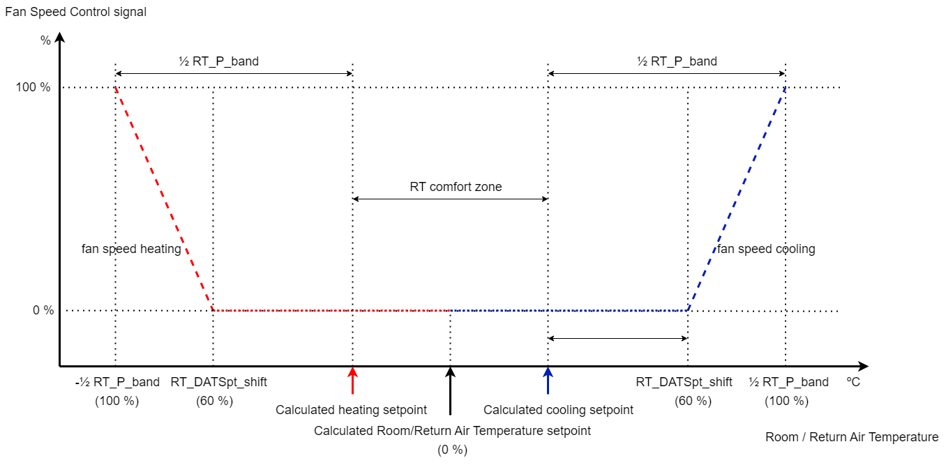
Fan speed control
Sequence Control of Dampers or Energy Recovery Equipment
Dampers or energy recovery control, based on the room/return temperature within the comfort zone (TempCtrlMode=3). The dampers or the energy recovery equipment will be controlled in sequence, based on the room temperature deviation and within the room temperature comfort zone. These sequencing actions are almost non-energy consuming but will help to keep the room temperature at the desired room temperature setpoint. The respective start- and end-point parameters for the dampers/energy recovery output signal are DAT_EnergyRecStart and DAT_EnergyRecEnd.
Notes:
The Y-signal of the dampers or energy recovery can be reversed by the economizer function, which was selected by the parameter EconomizerMode.
The end-point parameters must always have a higher value than the start-point parameters. If both start- and end-point parameters are set to 0, then that particular sequence function will be inactive.
The next figure shows the respective sequences within the room temperature comfort zone.
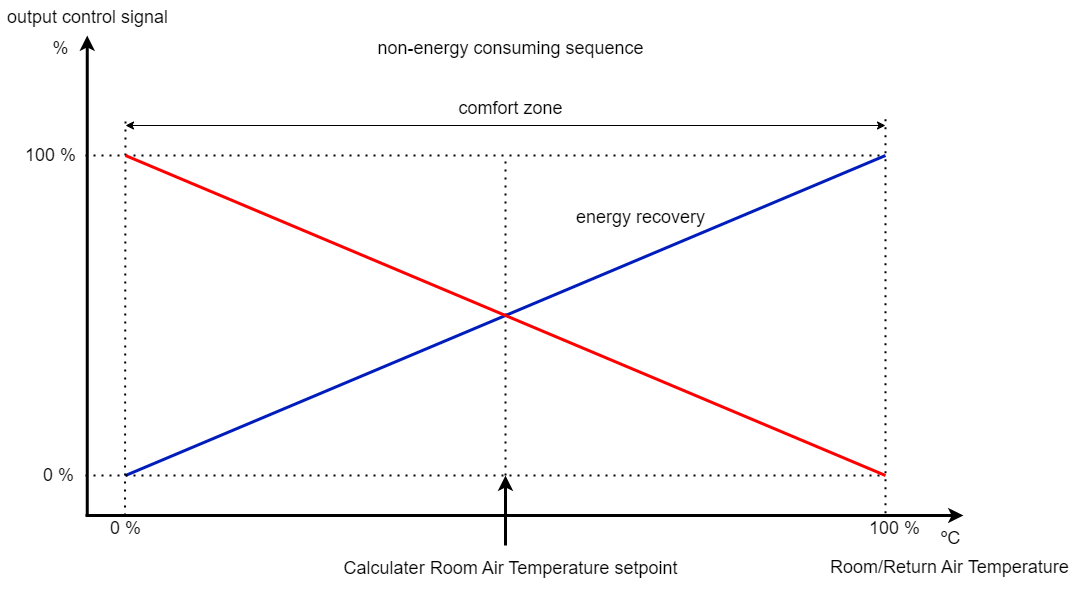
Non-energy consuming sequence
Fan Speed Control Based on Humidification
The fan speed can be increased when the humidification control signal increases from 0-100%. With parameters HUM_FanStart and HUM_FanEnd the sequence start- and end-point can be defined for the fan speed, as shown in the next figure.

Fan speed control based on humidification
Note: If the sequence start- and end-point parameter values are both set to 0, then this function will be inactive.
The variables HUM_Mode, and DEH_Mode, which are generated by the humidifier module, transmit the coded signal for humidification, dehumidification, or none of both (within the adjustable room relative humidity comfort zone of the humidifier module) into this Control module.
Code | HUM_Mode | DEH_Mode |
|---|---|---|
0 | No humidification | No dehumidification |
1 | 1=humidify | 1=dehumidify |
Intelligent Dehumidification Control
For this intelligent dehumidification control, it is recommended to make use of the economizer module, which provides the enthalpy override and the absolute humidity comparison. The parameter EconomizerMode, which defines the economizer function, should be set to the value 2, in this case. When the DEH_Mode coded signal from the humidity control. equals a value of 1, then dehumidification is active. Depending on the comparison of the absolute humidity between outside air and return/room air, it is possible to dehumidify by sequencing the dampers, the fan speed, and the cooling coil valve.
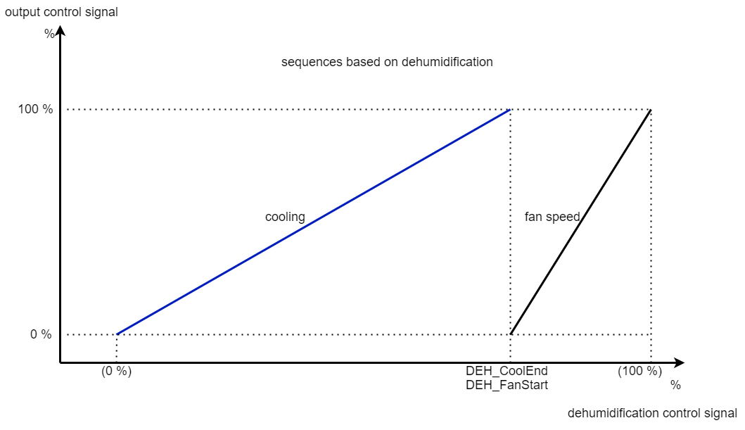
Sequencing Output Signals, Based on Dehumidification (OAx < RAx)
With the parameters DEH_-Start - DEH_-End the start- and end-point of the output control signals of the dampers, fan speed, and cooling can be adjusted based on dehumidification as shown in the next figure. It depends on the actual control signal, which controls mode, temperature, or dehumidify, and controls the respective output signals.

Sequences based on dehumidification
The respective sequencing parameters can be adjusted with gaps or overlaps as desired, as shown in the next example.

Sequences based on dehumidification
Note: The end-point parameters must always have a higher value than the start-point parameters. If both start- and end-point parameters of a sequence are set to 0, then that particular sequence function will be inactive.
Sequencing Output Signals, Based on Dehumidification (OAx > RAx)
Only in the case of parameter EconomizerMode having a value of 2 and if the outside air absolute humidity is higher than the room/return air absolute humidity, the fan speed and cooling coil sequence will be interchanged. So, the cooling coil valve will be modulated to the open position first and will then be sequenced with the fan speed. The start-point value of the cooling coil valve sequence is automatically set to 0% and the end-point value of the fan speed sequence at 100%. The sequence start- and end-points of the dampers are automatically set to 0, which means that damper sequencing is eliminated in this case. See the next figure.
Sequences based on dehumidification
CO2 Air Quality Override on Dampers and Fan Speed
If a CO2 sensor is connected to the input CO2 (for mixing dampers version), the air quality setpoint and the proportional band for the internal proportional controller can be defined in parts per million (ppm) by means of the respective parameters CO2Setpoint and CO2_P_band.
The total proportional band is shifted below the setpoint, as shown in the next figure.
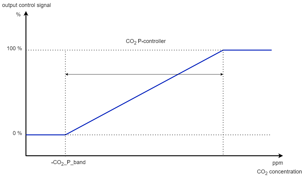
CO2 output control signal
The fan speed of a variable speed fan can be increased, when the air quality controller produces a signal that is higher than the start point of the CO2 override, defined by parameters CO2_-Start - CO2_-End. The next figure shows the air quality override function on the internal damper and fan speed control signal, which are finally maximized with other respective internal signals.
Note: The end-point parameters must always have a higher value than the start-point parameters. If both start- and end-point parameters of a sequence are set to 0, then that particular sequence function will be inactive.

Override based on CO2/air quality
Tip: Sometimes, the air quality device is an active controller with its own proportional band and setpoint, providing an output signal from 0-1 V or 0-10 V between a certain span, e.g., between 800-1000 ppm. This signal has to be converted into a 0-100 % signal in order to connect it to the input CO2. When the device measures the air quality, equal to the minimum value, then the input signal will be 0%. If air quality goes bad, up to the maximum value, the signal will raise up to 100 %.
WARNING: To disable the internal CO2 controller in this case, the value of parameter CO2Setpoint (=setpoint air quality control) must be set to 0.
Winter Compensation of Discharge Air Temperature Setpoint
To eliminate increased building transmission losses and from the comfort point of view (during the winter period), a higher discharge air temperature is desired. With decreasing outside temperatures, the discharge air temperature setpoint is reset as defined by parameters WC_DischStartComp and WC_DischEndComp.
The winter compensation raise is defined by parameter WC_DischSptRaise, shifting the discharge air temperature setpoint and the respective minimum and maximum limit setpoints DAT_LowSetpoint and DAT_HighSetpoint upwards.
Note: If parameter WC_DischSptRaise is set to 0, there will be no winter compensation.
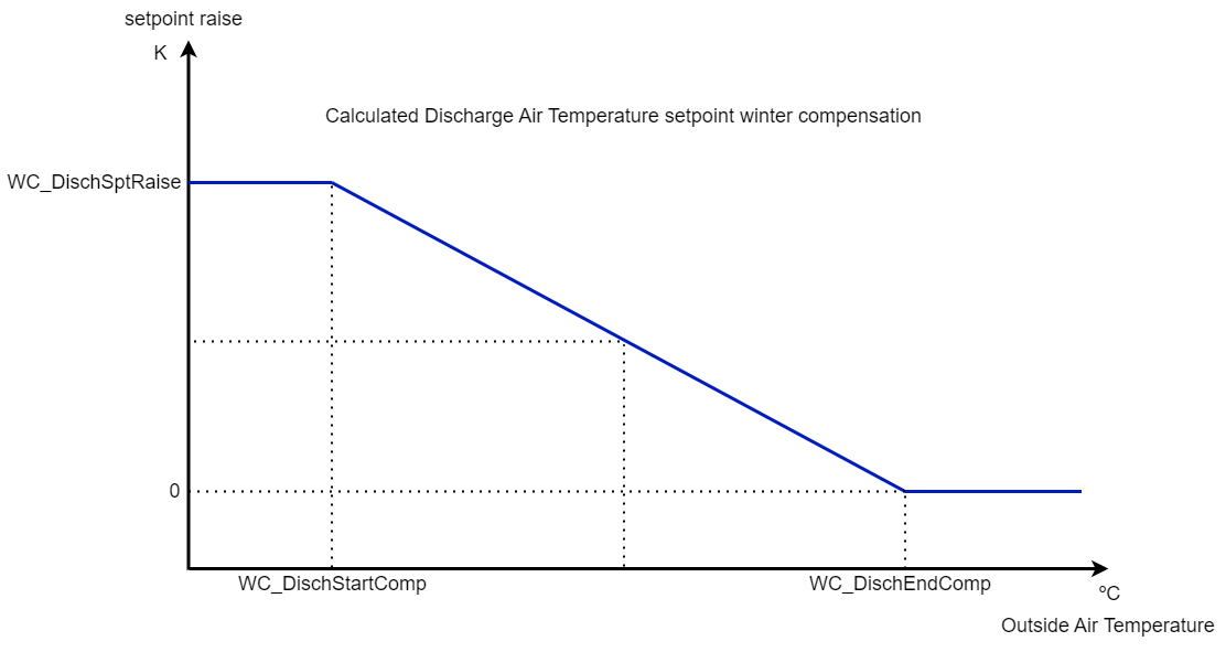
Calculated discharge air temperature setpoint winter compensation
Summer Compensation of Room Temperature Setpoint
To save cooling energy during the summer period, the room temperature setpoint is reset by the outside air temperature, defined by parameters SC_RoomStartComp and SC_RoomEndComp.
The summer compensation setpoint raise is defined by the parameter SC_RoomSptRaise.
Note: If SC_RoomSptRaise is set to the value of 0, there will be no summer compensation.
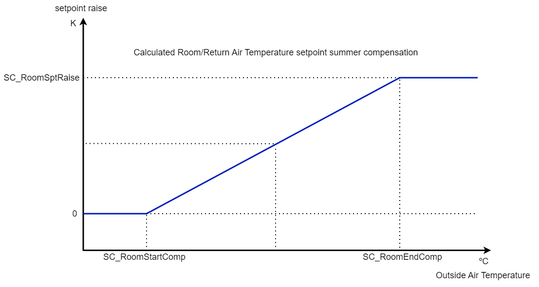
Calculated room/return air temperature setpoint summer compensation
Blocking Heater Valve During the Summer Season
During the summer, it is possible to block the heater valve at high outside air temperatures to save energy on the heating load. With parameter OAT_HeaterLimit the temperature can be defined, above which the heater valve will stay closed.
Note: The HTS output signal will be automatically released again if the coded signal DEH_Mode equals the value of 1 (dehumidification is needed).
Blocking the Cooling Valve During the Winter Season
During the winter, it is possible to block the cooling valve at low outside air temperatures to save energy on the cooling load. With parameter OAT_CoolerLimit the temperature can be defined, below which the cooling valve will stay closed.
Frost Protection/Frost Recovery After Frost Alarm
When the frost protection via the plant mode signal becomes active, the following action occurs:
all output control signals, except HTS, are set to 0%.
the HTS output is set to a value of 100%.
Frost protection actions are normally performed in the respective output modules.
When the frost failure has been reset, there will be a start-up procedure at low outside air temperatures. To prevent frost alarm again, the AHU with mixed air dampers will start on forced recirculation, followed by a temporarily raised discharge air temperature setpoint, which will be slowly decremented to the value of its normal discharge air temperature setpoint. The ramp-down time can be adjusted by the parameter DAT_SptDecTime. During forced recirculation, the DMS output signal will have a value of -1, which forces the damper output module to ignore its own minimum damper position adjustment.
Economizer Function for Cooling-load Savings
To save energy on cooling load, the energy recovery control signal can be reversed and the mixed air damper control can be reversed or set to a minimum position. With the parameter EconomizerMode, the economizer function of the energy recovery or dampers can be selected for different operating situations, as shown in the next table.
EconomizerMode setting | Economizer function |
|---|---|
None (0 on LCD) | Function disabled |
Eco Return Temp (1 on LCD) | If the room temperature is above the value of the calculated room temperature setpoint and the outside air temperature is higher than the return temperature behind exhaust fan (return air temperature sensor connected to input ReturnTemp). |
Eco Enthalpy (2 on LCD) | On absolute humidity and/or enthalpy override from the economizer module: DAMPERS: a) if HUM_Mode=1 and EnthalpyOverride=1, then the damper control signal will be reversed; b) if HUM_Mode=0 or DEH_Mode=1 and AbsHumOverride=1, then the damper control signal are set to minimum; c) if HUM_Mode=0 or DEH_Mode=2 and AbsHumOverride=0 and EnthalpyOverride=1, the damper control signal will be reversed. ENERGY RECOVERY: a) if EnthalpyOverride=1, then the energy recovery control signal will be reversed. |
Note: Air quality control override (CO2) has a higher priority than the economizer function.
Economizer Mode
The economizer mode override signals from the economizer module or the temperature comparison (inside the Control module itself) are used, for instance, to reverse the mixed air damper control signal and energy recovery control signal. In the case of absolute humidity comparison during dehumidification, the action of the mixed air dampers is inverted. With the parameter EconomizerMode, the economizer function is selectable.
Abs. X comparison | Code | Enthalpy comparison | Code |
|---|---|---|---|
OAx < RAx | 0 | OA enthalpy < RA enthalpy | 0 |
OAx > RAx | 1 | OA enthalpy > RA enthalpy | 1 |